4000 Evaluation Unit
Service Manual 4-53
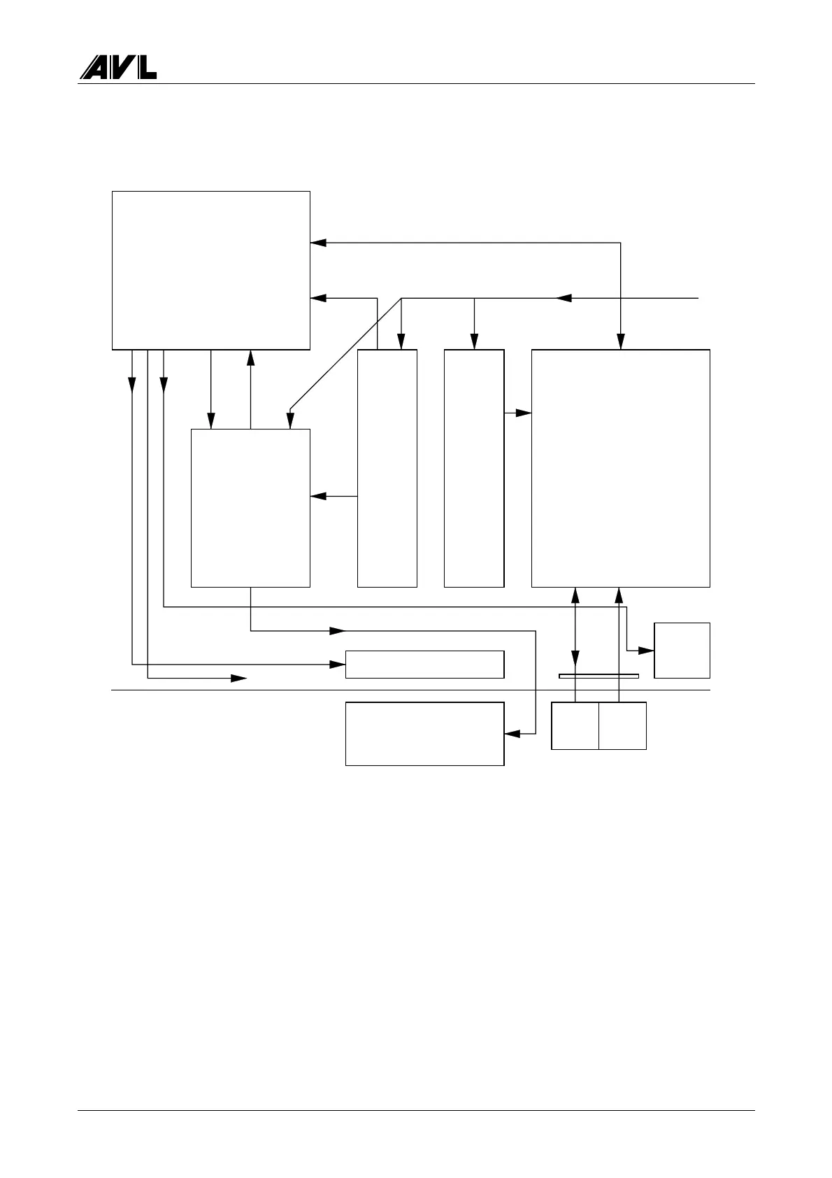
Wiring of the 4-/5-gas measuring instrument
1
2
3
45
6
7
8
9
10
11
12
13
11
1
Fig. 4-5
1 Mains connection 230 V / 50 Hz
2 Supply to Andros measuring system
3 RS232 Andros/AVL control
4O
2
sensor cable (shielded, 2-pin)
5NO/O
2
sensor cable for NO board (12-pin or 6-pin + cable item 4)
Supply to NO + signal
6 Supply to pneumatics module
7 Supply to AVL board
8 Pressure sensor signal 0…5 V
9 Pump control signal (TTL)
10 Supply to/control of fan 24 V DC
11 Control signal 24 V DC, zero solenoid valve
12 Supply to pump 230 V AC, control
13 Control signal 24 V DC, backflush
Sensor
NM
Zero
solenoid
valve
O
2
NOPump
Fan
Measuring system
Rear panel
Pneumatics
board
Pump
control
AVL main board
Power AVL
Power Andros
 Loading...