5-113
Chapter 5. DETAILED DESCRIPTION OF EACH FUNCTION
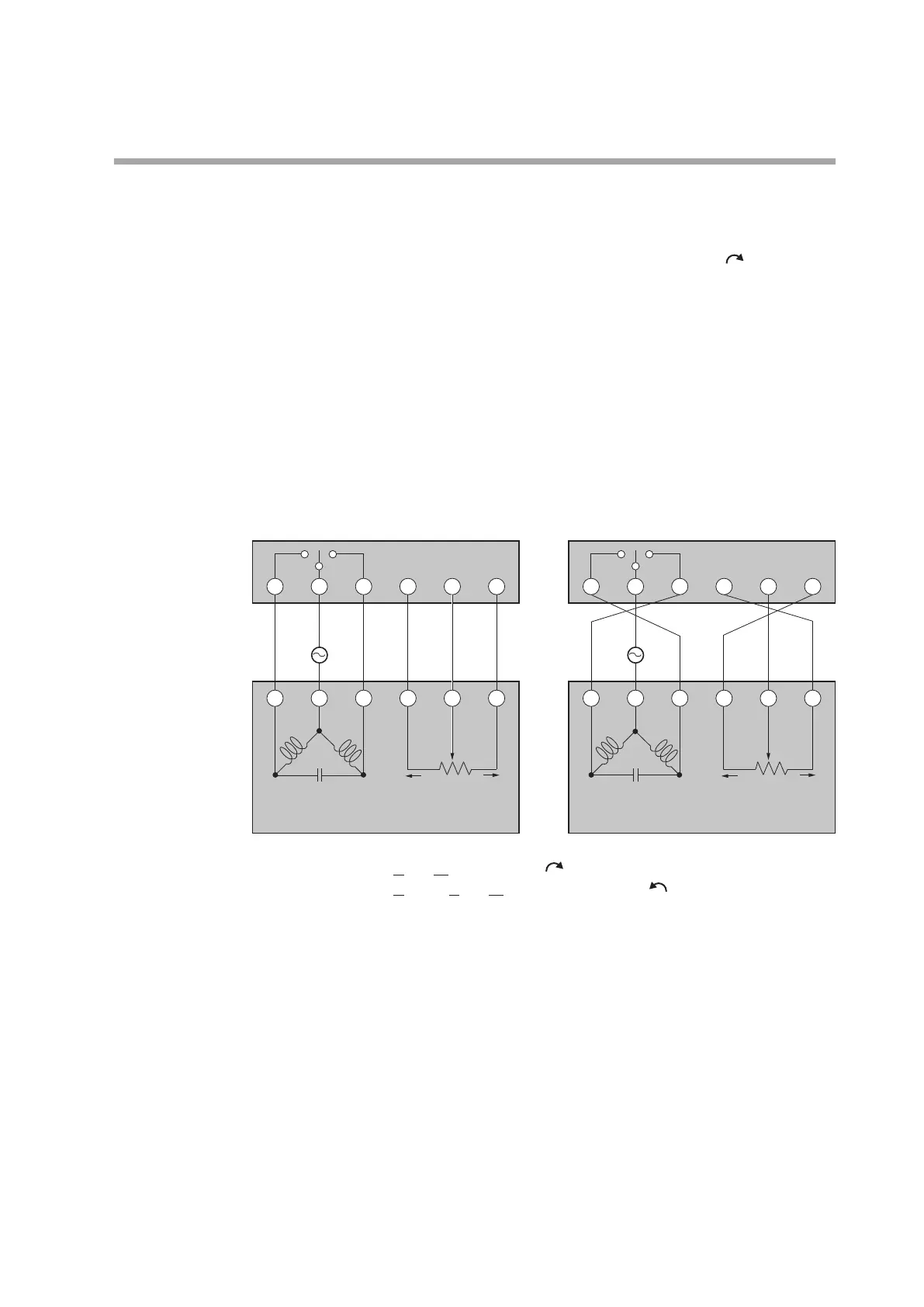
Motor wiring and motor auto adjust operation
For wiring method between the motor and controller, two kinds of wiring methods,
direct wiring and reverse wiring, are provided as described below.
The direct wiring means that the motor is rotated clockwise (CW,
) as the output
of the controller increases.
If it is required to rotate the motor counterclockwise according to the control
contents, such as cooling control, two kinds of methods are provided as described
below.
• The wiring is not changed and the control action direction is changed on the
controller side.
• The wiring is changed to construct the reverse wiring.
In this unit, the control action (Direct/Reverse) can be changed.
If the direct wiring is used for the wiring to the motor, the thinking way of each
control is simplified and the trouble can be solved easily.
Therefore, it is recommended to perform the direct wiring where possible.
8
7
14 9
This unit
3
AC 24 V
2 1 Y
CW
CCW
T
G
CW
Open
CCW
Close
Motor
This unit
3
AC 24 V
T
CW
Open
CCW
Close
Motor
2 1
G
Y
Direct wiring Reverse wiring
7
8 913 14 15
13 15
CW
CCW
CW: Clock Wise (Clockwise, )
CCW: Counter Clock Wise (Counterclockwise, )
This unit has functions (
AL07
,
AL
10
) that detect incorrect wiring with the motor
and the MFB burnout or short-circuit.
In the same manner as described for the direct wiring, the unit judges the reverse
wiring as correct and does not give any alarm.
Additionally, when [
C57
: Position proportional type] is set at [0: MFB control
+ estimated position control], the operation continues even though the MFB
burnout is detected.
The following Tables summarize symptoms of each wiring method during motor
auto adjust ([
C60
: Motor adjust] is set at [1: Start]).
At this time, note that the motor is started from the fully closed position (position
where the motor rotated counterclockwise fully). Numeric values shown in the
lower display column of the Tables show examples. The lit LED column in the
Tables shows examples with initial values of the DO Assignment, that is, control
output 1 uses the open side and control output 2 uses the close side. Additionally,
the alarm is shown after the motor has been closed or opened fully.

 Loading...


