3-1
Chapter 3. INSTALLATION
CAUTION
Use this device within the operating ranges recommended in the specifications (temperature,
humidity, voltage, vibration, shock, mounting direction, atmosphere, etc.).
Failure to do so might cause fire or faulty operation.
Do not block ventilation holes.
Doing so might cause fire or faulty operation.
Installation locations
Choose an installation location with the following characteristics:
• With the exception of supply power and relay contact output, the I/O common
mode voltage to ground must be 30 Vrms max., 42.4 V peak max., 60 V DC max.
• Not subject to high or low temperature/humidity.
• Free from cilicone gas and other corrosive gases such as sulfide gas.
• Little dust or soot.
• Appropriate protection from direct sunlight, wind or rain.
• Little mechanical vibration or shock.
• Not under high voltage lines or near welding machines or other sources of
electrical noise.
• At least 15m away from high voltage ignition device for a boiler, etc.
• Not subject to strong electromagnetic fields.
• No flammable liquids or fumes.
• Indoors
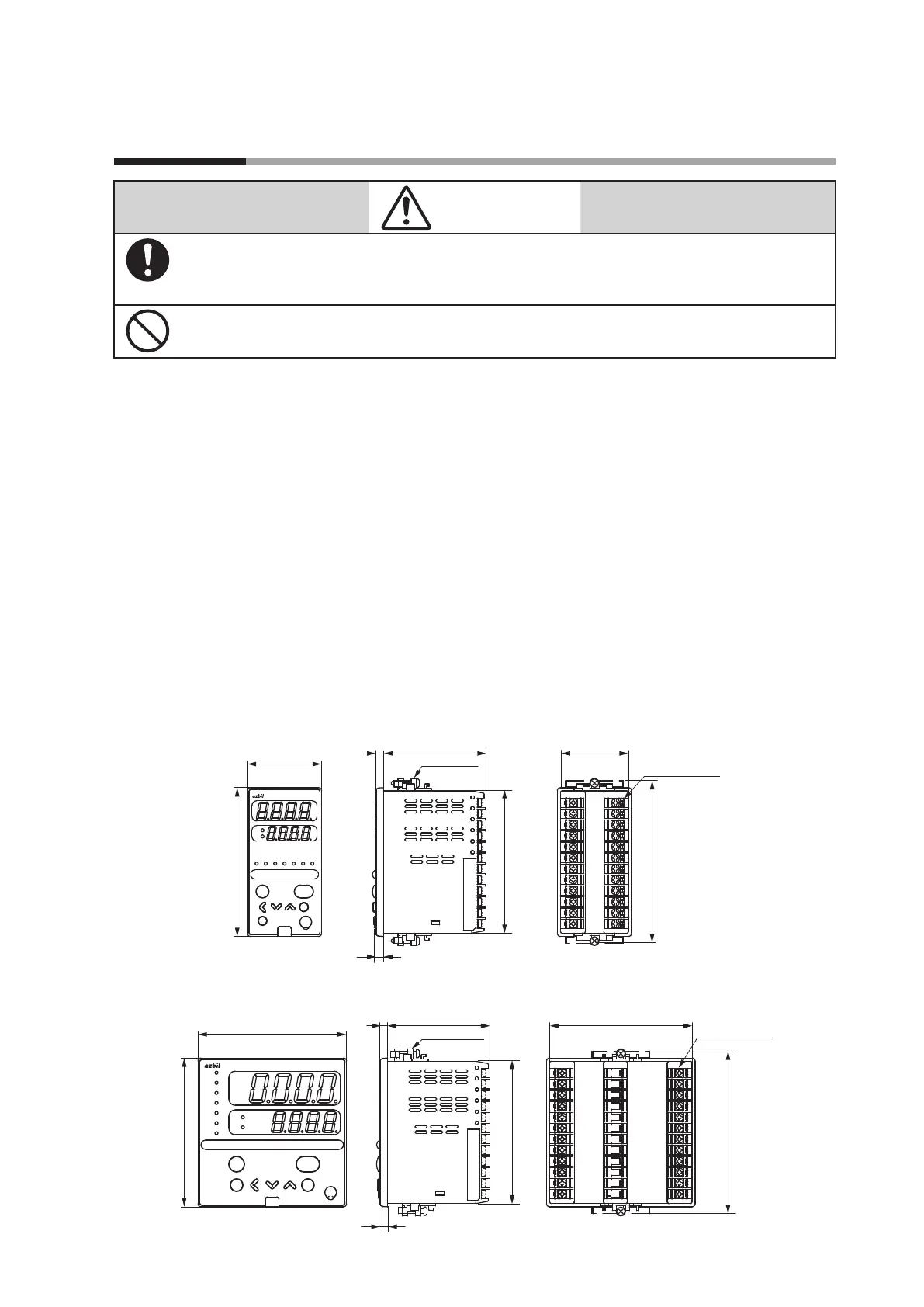
External dimensions
C35
Unit: mm
para
enter
display
mode
pv
out
sp
105
5
7.2
65 43.8
96
48
ot2ot1ev3ev2ev1rspman
SDC35
91.8
Mounting bracket (Accessory)
Terminal screw M3
C36
Unit: mm
mode
display
enter
para
man
rsp
ev1
ev2
ev3
ot1
ot2
sp
out
pv
SDC36
65
5
105
96
96
91.8
91.8
7.2
Mounting bracket (Accessory)
Terminal screw M3