1-4
Chapter 1. OVERVIEW
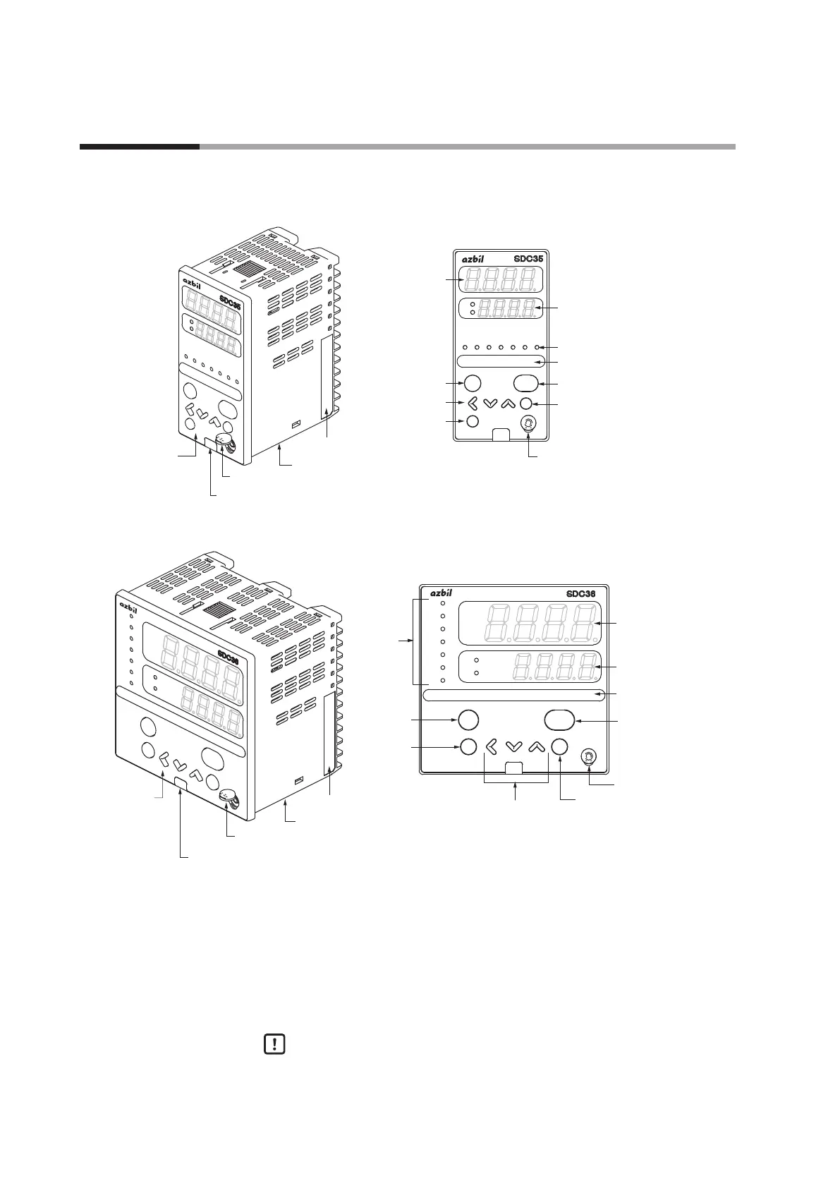
Main unit and console
C35
sp
out
pv
man rsp ev1 ev2 ev3 ot1 ot2
mode
display
enter
para
Console
Cap
Jack cover
Main unit
[mode] key
Loader connector
Lower display
Multi-Status (MS) display
[enter] key
Mode indicator
[display] key
Upper display
[<], [ ], and [ ] keys
[para] key
<
<
Model No. and serial No. label
C36
para enter
display
mode
pv
out
sp
ot2
ot1
ev3
ev2
ev1
rsp
man
Console
Cap
Main unit
Jack cover
[mode] key
Loader connector
Lower display
Multi-Status (MS)
display
Upper display
[enter] key
Mode
indicator
[display] key
[<], [ ] and [ ] keys
[para] key
<
<
Model No and serial No. label
Main unit: Contains the electronic circuit for I/O signals of measuring
instruments, CPU, and memory.
Console: Contains the display panel showing numeric value and status, and
operation keys.
Cap: Covers the slit, which is used to pull out the console from the main
unit.
Handling Precautions
The user must not touch the cap. This cap is used only by Azbil
Corporation’s engineers when repairing this controller. If the cap is pulled
forcibly, this may be broken.
1 - 2 Part Names and Functions