5-32
Chapter 5. DETAILED DESCRIPTION OF EACH FUNCTION
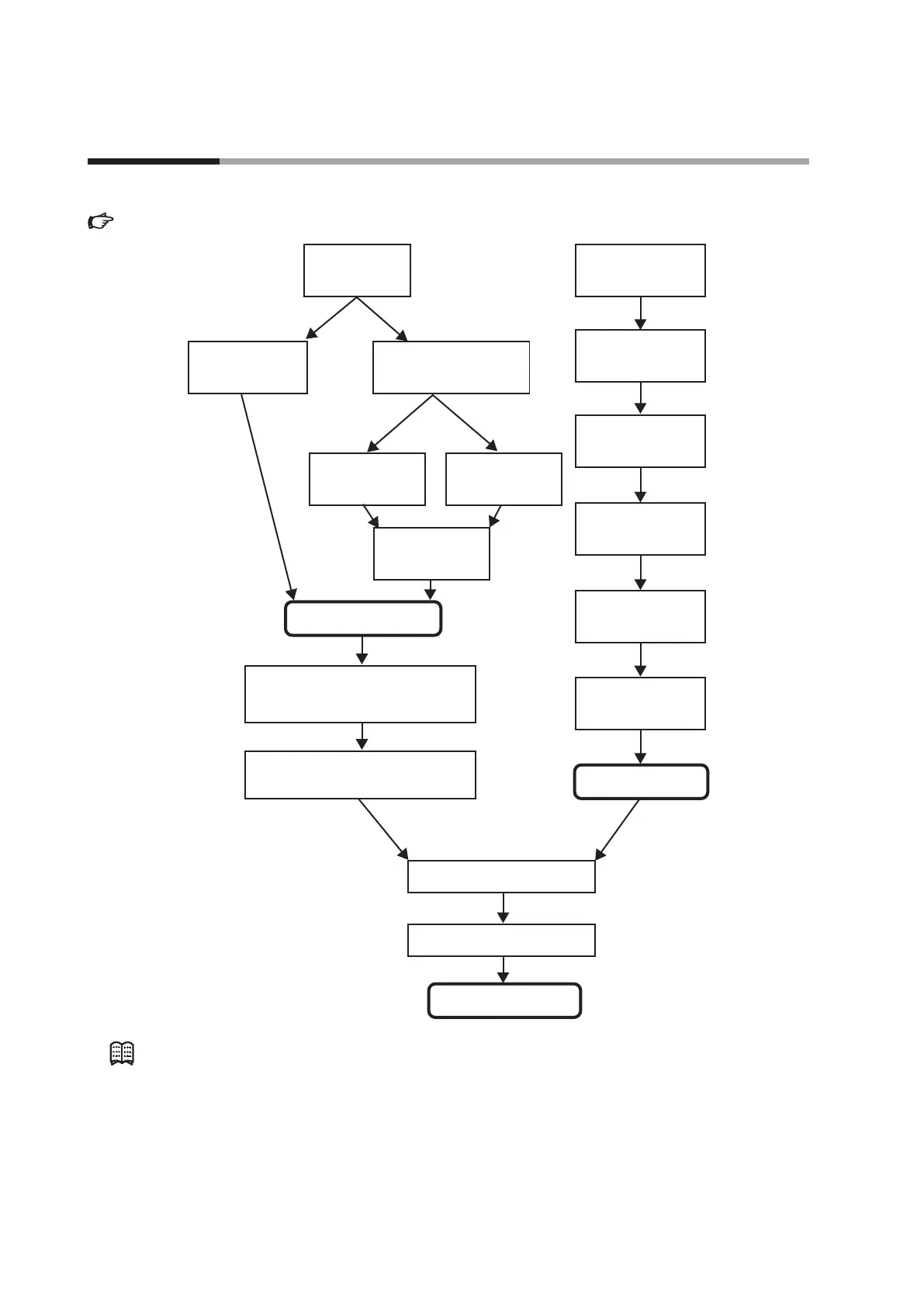
The following shows the functional block diagram of the SP. For details about step operation,
5 - 6 Step Operation (p.5-43).
One LSP group exists.
Two or more LSP groups exist.
LSP system group
(Setting: Setup C30)
LSP1
(Setting: SP SP 1)
DI Assignment is
not provided.
DI Assignment is
provided.
LSP value in use
SP
RSP
DI Assignment of LSP group
selection provided/not provided.
(Setting: DI Assignment di 1. 1
to di 5. 1)
LSP group number
(Setting: LSP group
number in operation
display mode)
Logical operation of DI
(Setting: General DI
Assignment)
RSP input type
(Setting: Setup C 10)
RSP high limit/low limit
alarm
(RSP mode only)
RSP scaling
(Setting: Setup C 1 1 to C 12)
RSP ratio
(Setting: Parameter rA2)
RSP bias
(Setting: Parameter bI 2)
RSP high limit/low limit
(-10 to +110 % of scaling)
LSP/RSP mode selection
SP high limit/low limit
(Setting: Setup C07, C08)
SP ramp unit (Setting: Setup C32)
SP ramp-up/ramp-down (Setting: Parameter
SPU, SPd)
DI Assignment of SP ramp enabled/disabled.
(Setting: DI Assignment di 1. 1 to di 3. 1)
LSP 1 to 8
(Setting: SP SP 1 to SP8)
Note
LSP is a local SP and shows that the data is retained inside this unit.
On the contrary, SP by the analog input from the outside is called RSP or remote SP.
5 - 5 Set Point (SP)