5-87
Chapter 5. DETAILED DESCRIPTION OF EACH FUNCTION
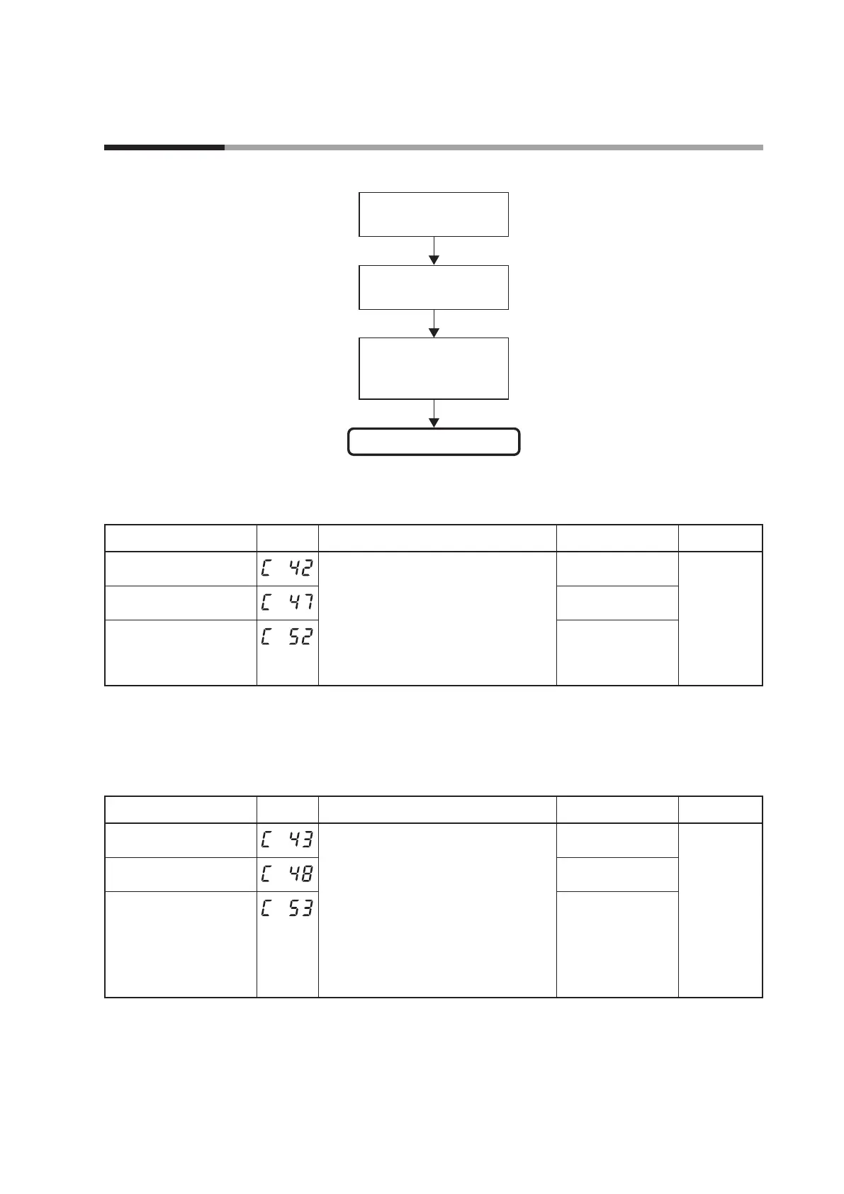
The following shows the functional block diagram of the continuous output:
(Setting: Setup
C42,
C47
,
C52
)
Continuous output (current output/
continuous voltage output)
Output range type
(Setting: Setup
C43
,
C48
,
C53
)
Output type
(Setting:
C44
,
C45
,
C49
,
C50
,
C54
,
C55
)
Output scaling high limit/low limit
Output range
The output range of the current output and continuous voltage output can be set.
Item (Bank) Display Contents Initial value User level
Control output 1 range
(Setup bank)
Current output
1: 4 to 20mA
2: 0 to 20mA
1 Basic,
Standard,
High function
Control output 2 range
(Setup bank)
1
Auxiliary output range
(Setup bank)
Continuous voltage output
1: 1 to 5V
2: 0 to 5V
3: 0 to 10V
1
• When the object control output is the current output or continuous voltage
output, the display and setting can be configured.
Output type
The output type of the current output and continuous voltage output can be set.
Item (Bank) Display Contents Initial value User level
Control output 1 type
(Setup bank)
0: Manipulated variable (MV)
1: Heat MV (for heat/cool control)
2: Cool MV (for heat/cool control)
3: PV
4: PV before ratio, bias, and filter
5: SP
6: Deviation (PV-SP)
7: CT1 current value
8: CT2 current value
9: MFB (including estimated MFB)
10: SP+MV
11: PV+MV
0 Basic,
Standard,
High function
Control output 2 type
(Setup bank)
3
Auxiliary output type
(Setup bank)
3
• When the object control output is the current output or continuous voltage
output, the display and setting can be configured.
• MV scalable bandwidth is used to calculate SP+PV and PV+MV. For details, refer
to MV scaling range (on page 5-89).
• If ROM version 1 of the instrument information bank is prior to 2.04, SP+MV
and PV+MV cannot be selected.
5 - 11 Continuous Output