5-12
Chapter 5. DETAILED DESCRIPTION OF EACH FUNCTION
5 - 3 Control
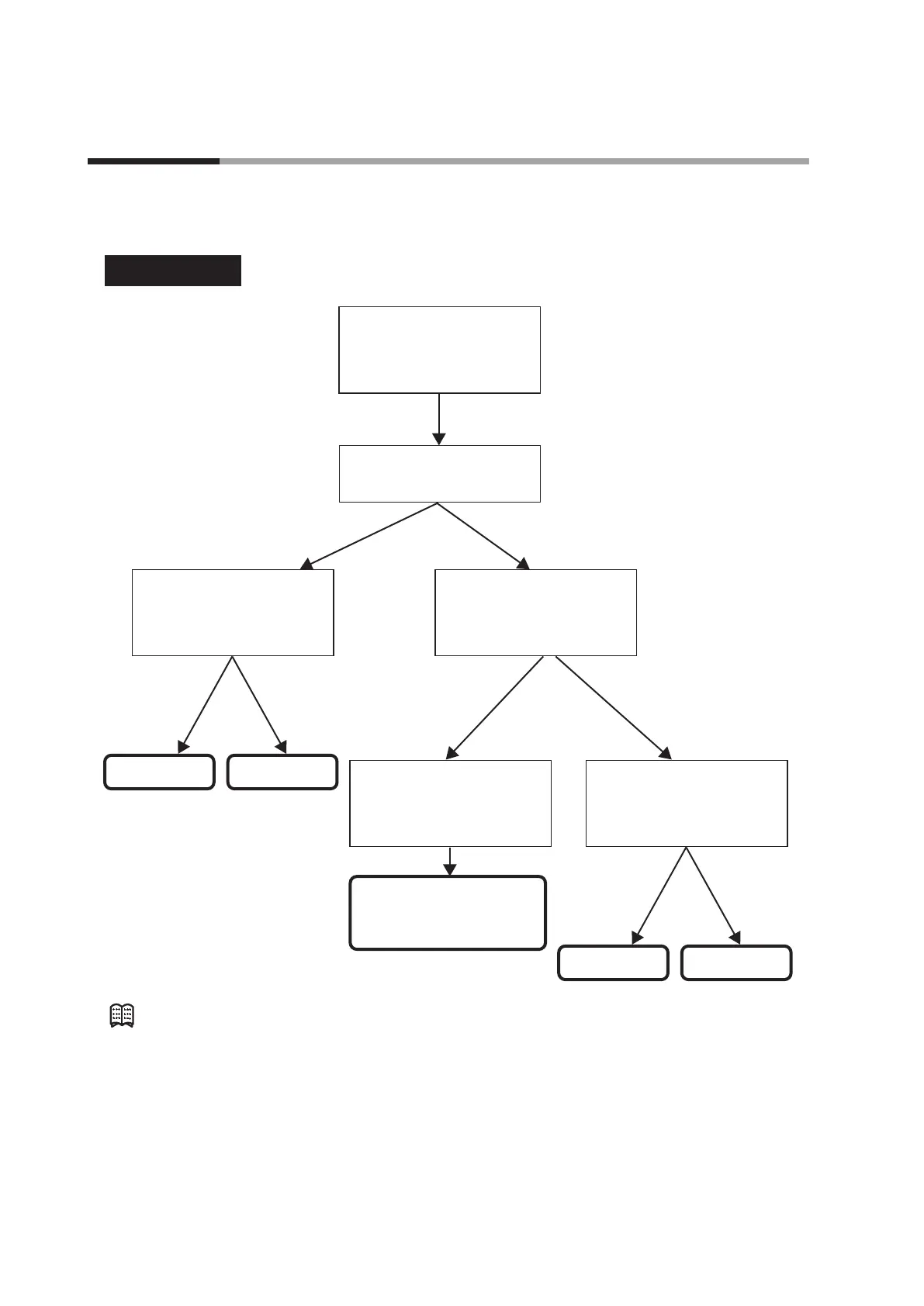
The following shows the functional block diagram of the control (ON/OFF control, PID control, RationaLOOP
control, and Heat/Cool control, etc.):
MV1 output ON MV1 output OFF
MV1 output ON or output OFF
ON/OFF control
Control method: ON/OFF control
(Setting: Parameter CtrL
must be set at "0".)
ON/OFF control
(Setting: Parameter dI FF, OFFS)
Branching according to
output at READY
(Setting: Setup C 1 7)
Branching according to
output operation at PV alarm
(Setting: Setup C 15)
Branching according to
RUN/READY mode selection
READY mode
C 1 7 > 0.0 % C 1 7 ≤ 0.0 %
MV1 output ON MV1 output OFF
Branching according to
output at PV alarm
(Setting: Setup
C 16)
C 16 > 0.0 % C 16 ≤
PV is correct or
C 15 = 0:
PV is faulty (AL01/02 occurs)
and C 15 = 1:
RUN mode
Note
When the control output type is R1 (motor drive relay output), the ON/OFF control
is not enabled.