6-1
Chapter 6. LIST OF DISPLAYS AND SETTING DATA
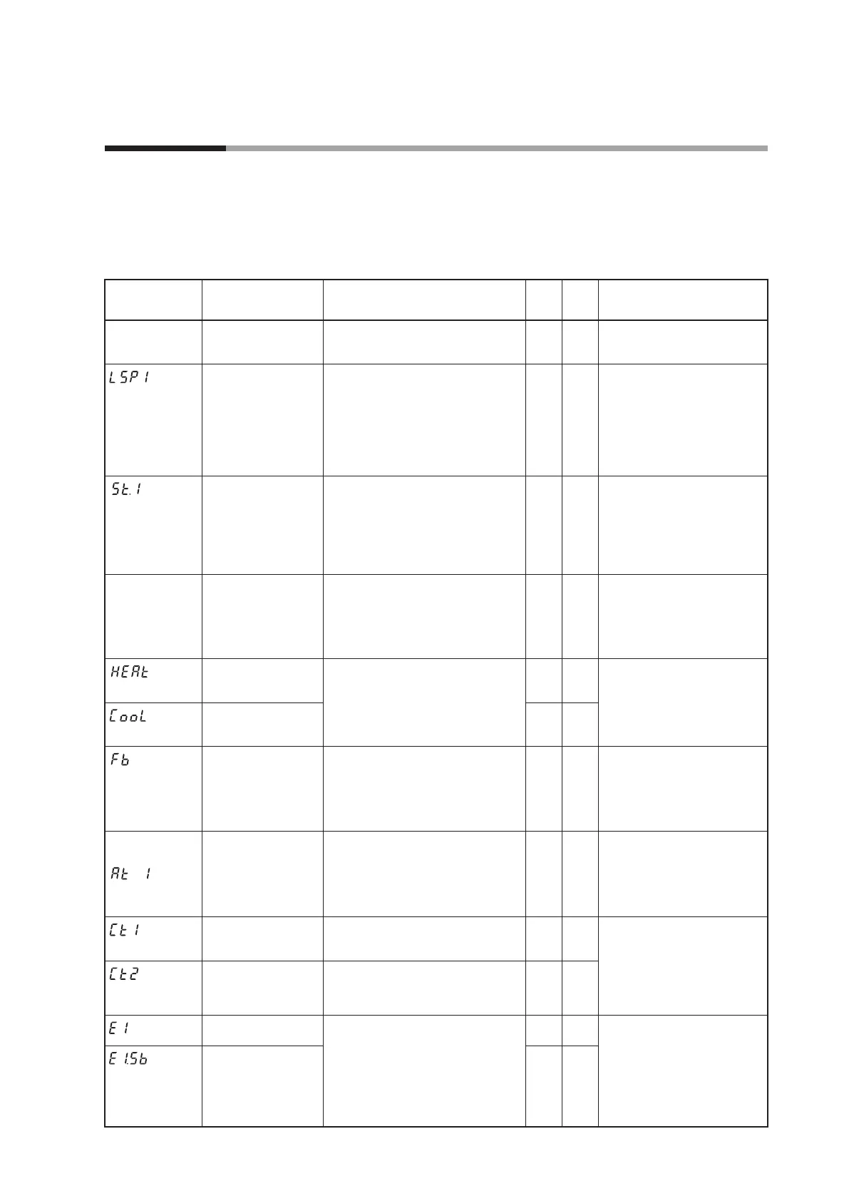
6 - 1 List of Operation Displays
The following shows the meanings of the values stated in the “User Level” column:
0: Basic, Standard, and High function configuration
1: Standard and High function configuration
2: High function configuration
Operation displays
Display Item Contents
Initial
value
User
level
Notes
Upper display: PV
Lower display: SP
SP (Target value)
SP low limit (
C07
) to SP high limit
(
C08
)
0
0
Whether or not this item is
displayed is selected by the
PV/SP display setup (
C74
).
(Display
example)
Lower display:
LSP
LSP No.
(1st digit: Value at
the right end digit)
1 to LSP system group (
C30
, Max. 8)
1 0
Displayed when LSP system
group (
C30
) is “2” or more.
The lower display shows the
LSP set value corresponding
to the LSP group number.
Whether or not this item is
displayed is selected by the
PV/SP display setup (
C74
).
(Display
example)
Lower display:
Step remain time
Step operation
remaining time
Setting is disabled.
Upper display shows the step No. (1
to 8), and distinction among the soak,
up ramp, and down ramp on the
right of “
St.
”. Lower display shows
the soak remain time or ramp remain
time.
1
0
Regardless of the soak or ramp
operation, the remain time
is displayed in step time unit
(setup
C33
). When the unit is
1s, “min.s” is displayed. When
the unit is 1min, “h.min” is
displayed.
Upper display:
PV
Lower display:
MV
MV (Manipulated
Variable)
-10.0 to +110.0 %
Setting is disabled in AUTO mode.
(Numeric value does not flash.)
Setting is enabled in MANUAL
mode. (Numeric value flashes.)
— 0
In the ON/OFF control (
CtrL
= 0), "100.0" is displayed at
ON and "0.0" is displayed at
OFF. Whether or not this item
is displayed is selected by the
MV display setup (
C75
).
Heat MV
(Manipulated
Variable)
Setting is disabled.
-10.0 to +110.0 %
— 0
This item is displayed when
using the Heat/Cool control
(
C26
= 1).
Whether or not this item is
displayed is selected by the
MV display setup (
C75
).
Cool MV
(Manipulated
Variable)
— 0
MFB (Motor opening
feedback value)
Setting is disabled.
-10.0 to +110.0 %
Flashing when the value is 0.0 to
100.0% during estimate.
— 0
Displayed during execution of
AT. (The display is continued
even after completion of AT.)
Whether or not this item is
displayed is selected by the
MV display setup (
C75
).
Upper display:
PV
(Display
example)
AT progress display
(1st digit = Numeric
value at right end
digit)
Setting is disabled.
Lower display shows the AT
progress value on the right of “
At
”.
1 - : During execution of AT (Value is
decreased.)
0: Completion of AT
— 0
Displayed during execution of
AT. (The display is continued
even after completion of AT.)
Whether or not this item is
displayed is selected by the
MV display setup (
C75
).
CT (Current trans-
former) current
value 1
Setting is disabled.
— 0
Displayed when the optional
model has two current
transformer points.
Whether or not this item is
displayed is selected by the
CT input current value display
setup (
C78
).
CT (Current trans-
former) current value 2
Setting is disabled.
— 0
Internal Event 1
main setting
The allowable setting range may
vary depending on the operation
type of the internal event.
-1999 to +9999 U: Set value is other
than the following values:
0 to 9999 U: Set value is an absolute
value.
-199.9 to +999.9 %: Set value is MV.
0 0
Setting required by the
operation type of the internal
event is displayed.
Whether or not this item is
displayed is selected by the
Event setting value display
setup (
C76
).
Internal Event 1
sub-setting
0 0

 Loading...


