5-58
Chapter 5. DETAILED DESCRIPTION OF EACH FUNCTION
The result of the internal event process can be output to the control output or event output through the digital
output (DO) process.
For details,
2 - 1 Input/Output Configuration (p.2-1).
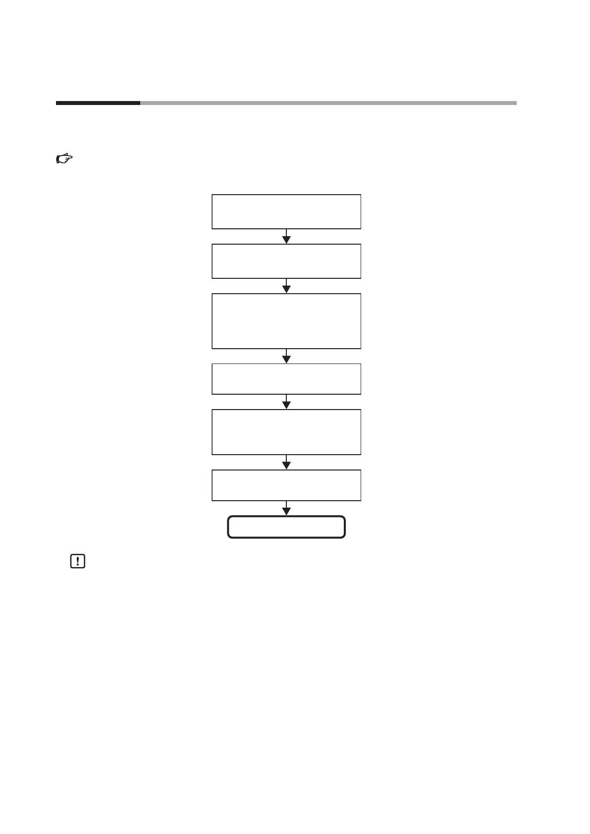
The following shows the functional block diagram of the internal event:
Operation type
(Setting: Event Conguration
Operation type E 1. C 1 to E8. C 1 )
Direct/reverse, Standby
(Setting: Event Conguration,
Direct/reverse, Standby E 1. C2 to E8. C2)
Controller alarm OR/AND
(Setting: Event Conguration
E 1. C3 to E8. C3)
EVENT state at READY
(Setting: Event Conguration
E 1.C2 to E8.C2)
Main setting, sub setting,
hysteresis, special OFF setup
(Setting: Event E 1 to E8, E 1.SB to E8.SB,
E 1.HY to E8.HY, Event Conguration
E 1. C3 to E8. C3)
ON delay, OFF delay, Delay time unit
(Setting: Event E 1.On to E8.On,
E 1.OF to E8.OF.
Event Conguration E 1.C3 to E8.C3)
Internal Event status
Handling Precautions
Even though eight internal events 1 to 8 are provided, the number of event
outputs determined by the optional model is 0 to 3 points. With the default
settings before shipment, the operations of internal events 1 to 3 can be output
to event outputs 1 to 3. To utilize the operations of internal events 4 to 8, it is
absolutely necessary to set the DO Assignment.
5 - 8 Internal Event

 Loading...


