4-11
Chapter 4. WIRING
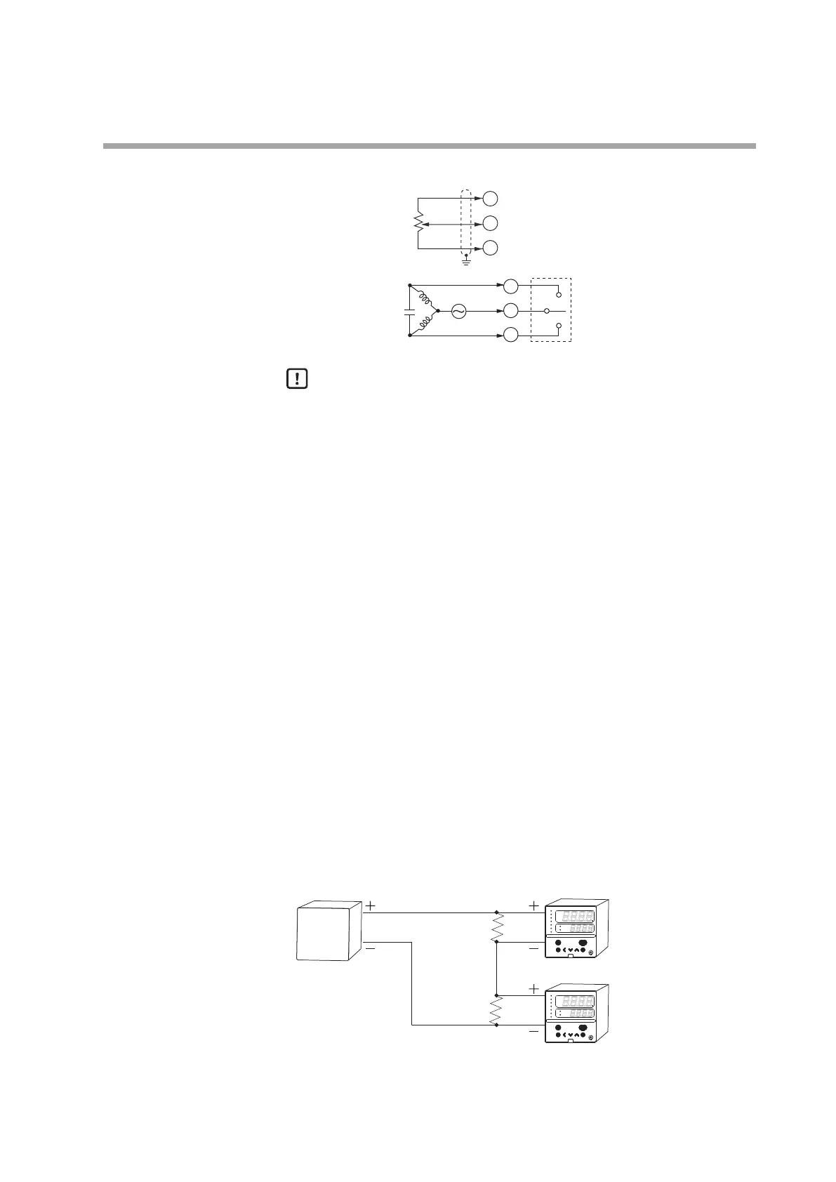
Connection method for the motor drive relay output (R1)
7
8
9
YOpen
Close
T
G
MFB
CLOSE
OPEN
13
14
15
Motor drive relay
Handling Precautions
• If connecting a 100 or 200 V AC motor to the motor drive relay output,
use an external auxiliary relay.
• Do not wire in the same duct for the motor drive terminals 13, 14, 15 and
the MFB input terminals 7, 8, 9 and also do not use 6-core cable.
Doing so might cause a malfunction due to motor start-up noise.
• Avoid setting the PID control such that the output excessively repeats
ON-OFF operations.
Doing so might shorten the life of the built-in relay.
If [
C59
: Motor long life mode] is set at “1,” the number of relay operations
can be reduced with almost no influence on the control results.
• When [
C57
: Position proportional type] is set at “2” or “3,” connections
to MFB terminals 7, 8 and 9 are not necessary. (This is the case of control
without a feedback function.)
• When [
C57
: Position proportional type] is set at “0” or “1” with motor
feedback function (MFB enabled), be sure to execute [
C60
: Motor adjust].
• When [
C57
: Position proportional type] is set at “2” or “3” without
motor feedback function (MFB disabled), be sure to input the value of
[
C63
:Motor full close-full open time] exactly.
Connection with current-input type controllers
When the power to this controller is turned off, the current input circuit is cut off.
If multiple current-input type SDCs are connected in series and you want to turn
them on/off individually, convert them to voltage input by adding resistors (No.
81401325, sold separately) to the circuit.
rdy
man
ev1 ev2 ev3 ot1 ot2
para
mode
pv
sp
SDC15
1 to 5 V
250 Ω
250 Ω
4 to 20 mA
1 to 5 V
SDC35/36
SDC35/36
Current output device
para enter
display
mode
pv
out
sp
ot2
ot1
ev3
ev2
ev1
rsp
man
SDC36
para enter
display
mode
pv
out
sp
ot2
ot1
ev3
ev2
ev1
rsp
man
SDC36
 Loading...


