BALTECH VP-3470
Operation manual
Technical description 19
4.4. Design and operation of the display
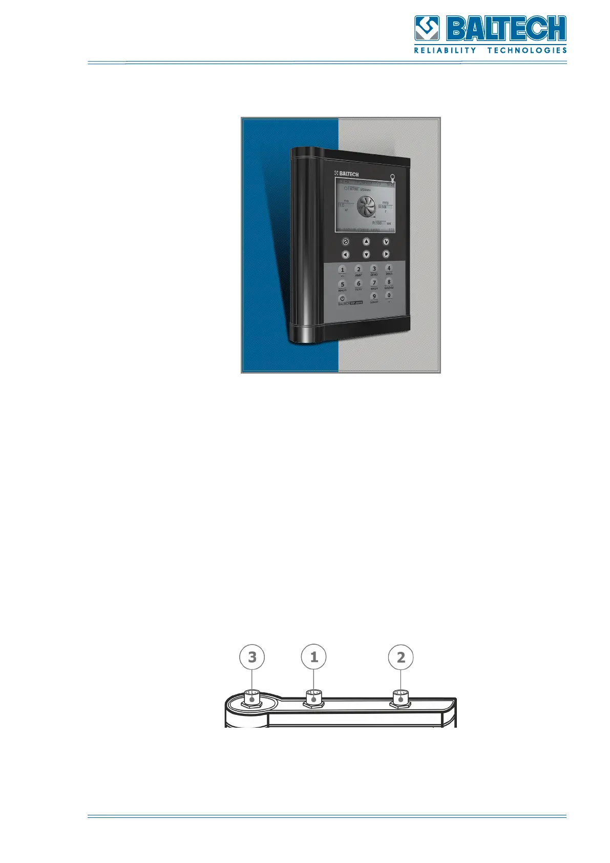
Figure 1. Appearance of the display unit
The display unit (Figure 1) consists of single-chip microcontroller with power
regulation circuits, color LCD 320 x 240 pixels, four LiFePO4 batteries and nonvolatile
memory for storage of reports and operation information.
There are two channels (01 and 02) on the top panel of the display unit for connecting
the vibration sensors (Figure 2). There is also an output for the tachometer and
stroboscope.
The output for the network adapter (1) and mini USB (2) are located on the lower
panel of the display unit (Figure 3).
Figure 2. Upper panel of the display unit
1. Input «01 channel»