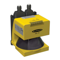
Banner AG4 Series Safety Laser Scanner
Machine control circuitry is designed so that one or more initiation devices must be engaged (i.e., a conscious
act is required) to start the machine – in addition to the Scanner turning ON its safety outputs (OSSD1 and
OSSD2).
or
It is not otherwise possible to access the hazard area, except while being continually detected by the Protective
Field.
1.12.2 Start Test
The start test function requires the operator to interrupt and then clear the Protective Field with a test rod after the
Scanner is powered up. Only then will the Scanner outputs turn ON, so the machine can be started. The function is
available only when Auto Reset is selected.
When the start test is combined with the automatic restart function, the start test serves as a start/restart signal.
1.12.3 Dust Suppression
The dust suppression function increases the reliability of the Scanner when small particles are in the air, e.g. material
chips or insects. Deactivate the dust suppression function when the Scanner must detect extremely fast or small objects
in the application.
1.12.4 Field Pairs: Independently Activated Protective and Warning Fields
Through the use of the Field Pair (FP) inputs, external logic (e.g., a PLC) is capable of selecting one of eight configured
Field Pairs stored in the Scanner at any given time. A Field Pair is defined as the combination of a configured Protective
Field (PF) and a Warning Field (WF). When active (see Table 1), a specific Field Pair is in sole control of the safety
outputs (OSSD1 and OSSD2) and the ALARM 1 auxiliary output. This function is useful to change the safeguarded area
in an application in which a hazard is not continually present or in mobile applications in which direction, speed and
stopping distance varies.
After the Scanner is configured, switching over or ―activating‖ an individual Field Pair is controlled by the four ―FP‖ inputs
on the Machine Interface X1 plug (see Table 1 and Figures 3-18, 3-19, and 3-20).
WARNING . . . PROTECTIVE FIELD PAIR SWITCHING
Field Pair Switching is used to temporarily suspend or change the area of safeguarding. Changing the Protective/Warning Field Pair from one
pair to another must not expose any individual to a hazard or hazardous situation. Supplemental safeguarding may be required.
In higher-risk applications, use redundant sensors or switches to initiate or enable a Field Pair change.
The conditions for switching Field Pairs must be in accordance with a risk assessment. Machine stopping/braking
distances, Scanner system response time (including interfacing devices), machine stop time and other factors that
influence the Safety Distance (Minimum Distance) and Stopping Distance calculations must be considered in order to
safely use the Field Pair Switchover function.
Conditions to Allow Switching Field Pairs:
Only one Field Pair can be active after the switchover time. See Field Pair Input Logic table 1.
Field Pair switchover is allowed even if there is an intrusion into the active Protective Field (i.e., OSSDs are
OFF).
The switchover must be made within one second, except when Field Pairs 5, 6, 7, or 8 are configured, at which
time the switchover must occur within 40 ms. In this case, the original Field Pair is active during the switchover;
the new Field Pair becomes active after a maximum of 80 ms. See timing diagram, Figure 1-9.
Buy: www.ValinOnline.com | Phone 844-385-3099 | Email: CustomerService@valin.com

 Loading...