Banner AG4 Series Safety Laser Scanner
Manipulating the Uploaded Configuration
The configuration can be changed via the wizard (Configuration Operating Mode tab highlighted: Configuration >
Wizard), or by manually changing settings and fields via the ―Configuration‖ and the ―Protective/Warning Fields
definition‖ Operating Mode tabs. See Section 4.2.2 or the AG4Soft manual for information on changing the
configuration.
See Section 4.4 for information on downloading a configuration to the Scanner.
Opening a Saved Configuration
Click on (highlight) the ―Configuration‖ Operating Mode tab, and then click on ―Load Configuration data from file‖ (6)
Operating Mode Icon to open a saved configuration to review or manipulate the configuration (e.g., the file saved in
Section 4.2.3 during the walk-through).
See Section 4.4 for information on downloading a configuration to the Scanner.
4.3.1 Establishing Communications Between the PC and the Scanner
Ensure that:
The AG4Soft program is open, then
The PC Interface cable (AG4-PCD9-xx) is connected to the X2 connector and the PC, and
Power is applied to the Scanner.
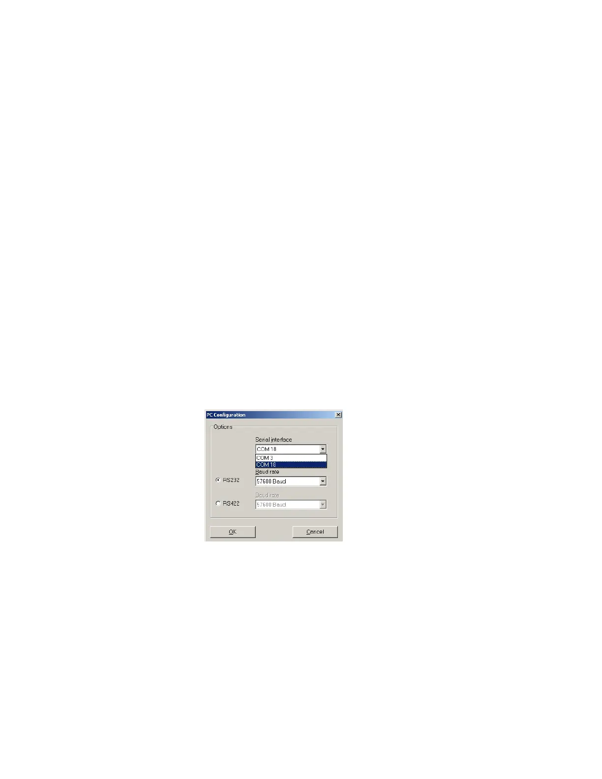
If communications are not established, a serial communications port may need to be selected. Highlight the
―Configuration‖ Operating Mode tab, then on the Menu Bar, click on ―Settings > PC configuration > Interface and
baud rate‖ to access the ―PC Configuration‖ window. Ensure that:
The ―Serial Interface‖ is set to the same port as that assigned to the Scanner interface by the PC Device
Manager > Ports (COM & LPT), (e.g., ―COM 18‖; the actual port will vary), and
The Baud Rate matches the PC Baud rate (e.g., 57600).
If this information needs to be identified or if configuring the PC serial port is required, see below.
The communication status displayed on the ―Status Line‖ should change from ―AG4 Synchron‖ to ―AG4 Connection‖.
―Synchron‖ means the PC is waiting for Scanner to synchronize, ―Connection‖ means the PC is in communication with
the AG4.
Once the connection is made, several dialog boxes may appear (follow instructions), and the ―Scanner status
information‖ window may also appear (click on EXIT after reviewing). Highlighting the ―Measure contour display‖
Operating Mode tab should display the measured area (yellow outline), the Warning Field, and the Protective Field.
Loss of Communication
If a loss of communication occurs, attempt a manual reset or cycle power, then:
1. Disconnect the AG4-PCD9-xx serial cordset at the AG4-PC9USB-1 (or at the Scanner's X2 connector)
2. Close the AG4Soft program
3. Connect USB cable at the PC (if used)
Buy: www.ValinOnline.com | Phone 844-385-3099 | Email: CustomerService@valin.com

 Loading...

