Banner AG4 Series Safety Laser Scanner
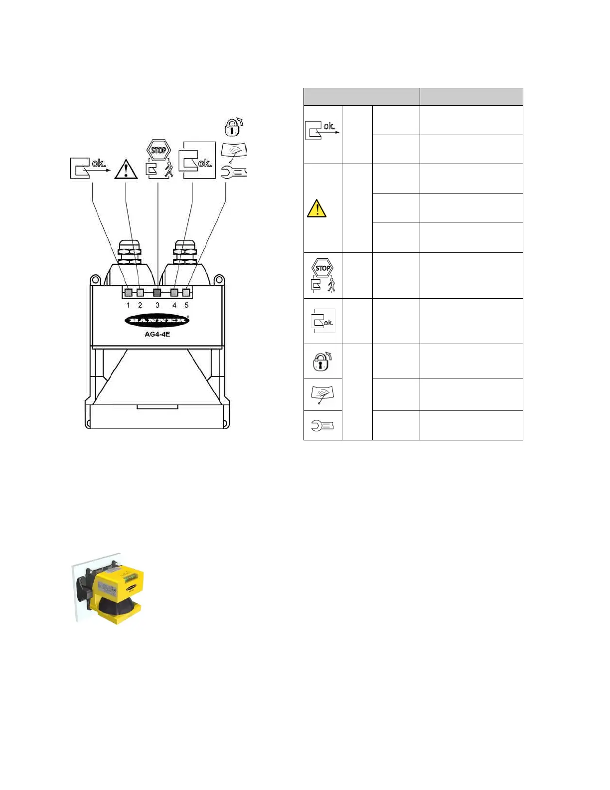
1, green
ON
Sensor function is active; the
active Protective Field is clear.
Fault on the Field Pair control
inputs.
2, yellow
ON
Active Warning Field is
interrupted.
Front screen is dirty.
ConfigPlug configuration is not
compatible with the Scanner.
3, red ON
Safety outputs (OSSD 1 and 2)
are switched OFF.
4, green ON
Safety outputs (OSSD 1 and 2)
are switched ON.
5, yellow
ON
Start/restart interlock is active
(reset required).
2 Hz
Front screen is dirty.
Fault
Figure 1-3. Status LEDs
1.2 Mounting System (Optional)
The AG4-MBK1 mounting system simplifies Scanner installation and alignment. The mounting system is available as an
accessory (see Section 2).
Figure 1-4. AG4 Scanner with AG4-MBK1 mounting system in place
1.3 Machine Interface X1 ConfigPlug
The ConfigPlug, included as part of the machine interface cables, is used to store the Scanner configuration and transfer
it to another Scanner. This simplifies the exchanging of a faulting or damaged Scanner. The plug saves the configuration
Buy: www.ValinOnline.com | Phone 844-385-3099 | Email: CustomerService@valin.com

 Loading...

