EasyManuals Logo

Banner AG4 Series User Manual

Banner AG4 Series
94 pages
To Next Page IconTo Next Page
To Previous Page IconTo Previous Page
Page #24 background imageLoading...
Page #24 background image
Banner AG4 Series Safety Laser Scanner
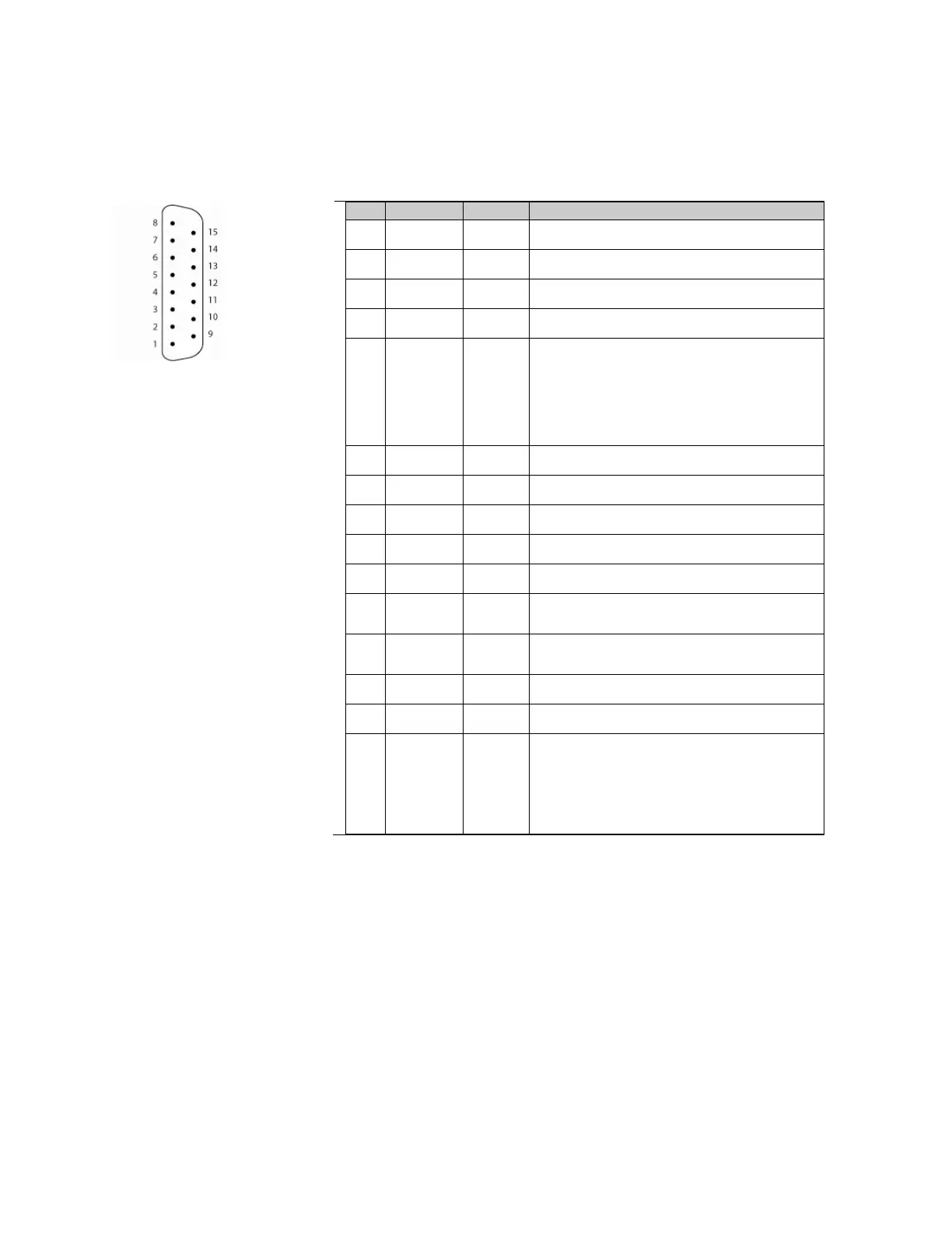
2.4 Connector Plug Assignments
X1 plug interface assignment
PIN
Color code
Signal
Description
1
blue
0V dc
24V dc common
2
violet
Reset
Input, start/restart (reset) switch connection
3
brown
+ 24V dc
Supply voltage
4
orange
FP 1
Input for activating Field Pair 1
5
white with black
stripe
Alarm 1 (Aux.
1)
Semiconductor output (PNP) with turn-OFF with:
Warning Field interruption
“Front screen dirty”
Internal fault
None (output held OFF)
See Section 1.12.6.
6
yellow
FP 2
Input for activating Field Pair 2
7
red
FP 3
Input for activating Field Pair 3
8
gray
FP 4
Input for activating Field Pair 4
9
Not connected
10
Not connected
11
black
OSSD 1
Semiconductor safety output channel 1, turn OFF with Protective
Field interruption
12
white
OSSD 2
Semiconductor safety output channel 2, turn OFF with Protective
Field interruption
13
Not connected
14
Not connected
15
white with
brown stripe
Alarm 2 (Aux.
2)
Semiconductor output with switch-off with:
“Front screen dirty
Internal fault
See Section 1.12.6.
Figure 2-3. X1 plug interface assignment
Buy: www.ValinOnline.com | Phone 844-385-3099 | Email: CustomerService@valin.com

Table of Contents

Other manuals for Banner AG4 Series

Questions and Answers:

Question and Answer IconNeed help?

Do you have a question about the Banner AG4 Series and is the answer not in the manual?

Banner AG4 Series Specifications

General IconGeneral
BrandBanner
ModelAG4 Series
CategoryScanner
LanguageEnglish

Related product manuals