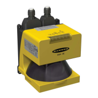
Banner AG4 Series Safety Laser Scanner
The cursor can also be used to click and drag to create a zoom box, in which the values of opposite corners are
displayed as the ―Position‖ and ―End position‖. Left-click to ―set‖ a point (Position). Right-click to ―finish‖ (End position).
X and Y values can be used to determine distance between two points by using the formula:
4.2.3 Configuration Wizard: Saving the Configuration
Saving the Entire Configuration, Including the Protective and Warning Fields (.rs file format)
When logged in as an ―Authorized Customer‖ (as noted on the status line tool bar), there are two primary methods to
save the configuration, which include the Protective and Warning Fields:
Using the Menu Bar with either the ―Configuration‖ or the ―Protective/Warning Fields definition‖ tabs highlighted
(yellow), click on File > Save configuration data as a file, or
Using the ―Configuration‖ Operating Mode Icon ―Save configuration data as a file‖ (7)
A Scanner's configuration file includes the following data:
Administrative data ( file name, application description )
Safety-relevant data, e.g., startup process
Protective Field or Warning Field configuration data (contours and limits)
The AG4Soft program will ask if you want to save a configuration if the ―Measured contour display‖ or ―System data‖ tabs
are selected and the configuration has not been previously saved.
Note: For the purposes of the "walk-through," save the configuration file as described above and proceed to Section 4.3.
Saving Only a Protective or Warning Field (.sf file format)
In case a mistake is made and an original starting point is needed or otherwise a record of each field is required, it can be
useful to individually save the Protective and Warning Field shapes as they are created.
At an appropriate time, such as before modifying the shapes of the Protective and Warning Fields, the field that is
displayed in the ―Select Protective/Warning Field‖ window (19) can be saved by clicking on File > Save
Protective/Warning Field as a file‖, or by clicking on the ―Save Protective/Warning Field as a file‖ (17) icon. The
―Protective /Warning Fields definition‖ operating mode tab must be highlighted (yellow) to access this save function.
4.3 Connecting the PC to the Scanner
Note: Ensure power is removed from the Scanner at this point, the AG4-PCD9-xx cordset is not connected to the PC,
and the AG4Soft program is open.
If not previously accomplished in Section 3.6.1, connect the PC Interface cable (AG4-PCD9-xx) to the X2 connector on
the Scanner and to the PC serial port. A USB-to-serial adaptor is available (AG4-PCD9USB-1) if the PC does not
provide a serial port (see below). If used, connect the AG4-PCD9USB-1 Serial-to-USB adaptor to a version 2.0 USB
port and then to the PC Interface cable (AG4-PCD9-xx).
The X1 Machine Interface connection should have been previously made (see Section 3.5). Depending on the situation,
it may be required that the machine be disabled with no power available to the machine actuators (Lockout/Tagout
regulations may apply, see Sections 3.5 and 3.7).
Apply power to the Scanner. After the Scanner has passed internal testing, communication is established (―AG4
Connection‖ is displayed on the Status line after approximately 30 seconds).
The current configuration automatically loads from the Scanner, the ―Change authorization level‖ dialog box appears
(it is recommended to be logged in as an ―Authorized customer‖, default password: bannera), and the status
information is ascertained from the Scanner. Review this information and click on ―Exit‖.
At this time the measured area (yellow outline), the Warning Field, and the Protective Field are displayed. The uploaded
configuration can be reviewed or manipulated, or a saved configuration can be opened and downloaded to the Scanner
as described in Section 4.4. If communications are not established, see Section 4.3.1.
Buy: www.ValinOnline.com | Phone 844-385-3099 | Email: CustomerService@valin.com

 Loading...