Banner AG4 Series Safety Laser Scanner
Field definition icons 20 through 23 are typically used to create general field shapes.
―Enter Protective/Warning Field numerically‖ (20) creates a rectangular field by entering a distance in millimeters to
the front edge and to both sides.
―Define elliptical Protective/Warning Field‖ (21) creates a semi-circular shape centered at the Scanner by left click
(hold) and then release. Click on the icon each time the field is to be changed.
―Define rectangular Protective/Warning Field‖ (22) creates a rectangular (square) shape with on edge centered on
the Scanner by left click (hold) and then release. Click on the icon each time the field is to be changed.
―Define polygonal Protective/Warning Field‖ (23) allows a point-to-point creation of an irregular shape by left-click to
plot each point (from left to right). A right-click completes the field.
Navigation Tool Bar
The values on the Working Space grid and in the Navigation Tool Bar (see below) can assist in plotting the location of
the points and the size of the fields. Please refer to Section 3.3.1 Needle and Cone-Shaped Fields for important
information.
The fields can be limited to 180º (i.e., the 0.000 meter mark on the vertical axis) if the area behind the Scanner is
otherwise guarded (see Section 3.3.1). This setting is found in menu bar path ―Settings > PC Configuration > 190º
Protective/Warning Fields‖ option (default is checked/enabled). Unchecking this option results in a 180º field and is
effective after the field shape has been changed.
Zoom in or out of an area by using ―minus‖ (1) and ―plus‖ (2) icons and the directional arrows on the Navigation Tool Bar,
or by drawing a box around the area of interest (left-click, hold to draw box, release). To resize and center the fields, click
on the center circle button on the Navigation Tool Bar.
If a field definition icon is clicked on by mistake, use the ESC key to deselect the icon. There is no ―undo‖ function;
please refer to the AG4Soft manual for further information on changing and adjusting the Protective and Warning Fields.
In most stationary applications, a ―reference boundary‖ must be defined. Icons 28 and 29 are used to create and modify
this function that prevents the miss-adjustment or misalignment of the Scanner. For the purpose of the walk-through, a
reference boundary will not be programmed; refer to the AG4Soft manual for further information
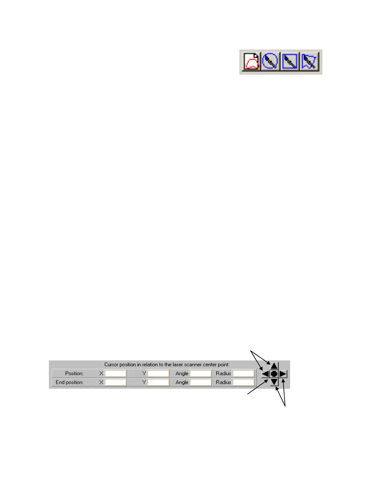
Navigation Tool Bar
In the x-axis and y-axis the cursor can be used to determine approximate field measurements.
Moves blue circle cursor up or left
(fields move down or right)
Moves blue circle cursor down or
right (fields move up or left)
Center circle
maximizes field display
Buy: www.ValinOnline.com | Phone 844-385-3099 | Email: CustomerService@valin.com

 Loading...

