Banner AG4 Series Safety Laser Scanner
3.6.1 Initial Power-Up and Configuration of the Scanner
Verify that:
Power has been removed from (or is not available to) the guarded machine, its controls or actuators;
The machine control circuit or the safety module is not connected to the OSSD outputs at this time (permanent
connections will be made later);
The slide switch in the Machine Interface X1 plug housing is set to the "1" (left) default position (if previously not
accomplished, see Section 3.5.1); and
The PC Interface cable (AG4-PCD9-xx) is connected to the X2 connector on the Scanner (if not previously
accomplished), but is not connected to the PC serial port.
If used, install the AG4-PC9USB-1 Serial-to-USB adaptor to a version 2.0 USB port on the PC, but not to the PC
Interface cable (AG4-PCD9-xx).
Open the AG4soft program and log in as an ―Authorized Customer‖. If not previously accomplished, configure the
Scanner as described in Section 4.2 (or the AG4Soft manual). Connect the PC via the PC Interface cable
(AG4-PCD9-xx) to a serial port or to the AG4-PCD9USB-1 Serial-to-USB adaptor. Apply power to the Scanner.
Status information can now be uploaded and the configuration can be downloaded to the Scanner. (See Section 4.)
3.6.2 Initial Optical Field Verification
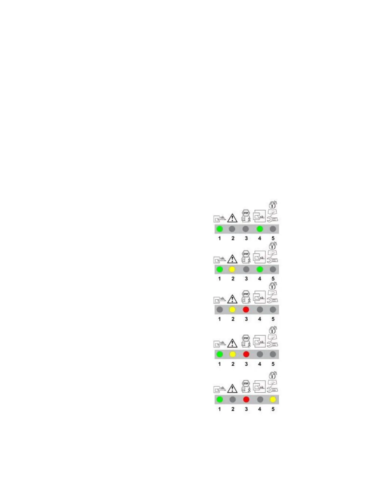
Table 8. Typical LED indications shown below (assumed Warning Field controls Alarm 1).
a) Protective and Warning Fields clear
- OSSD and Alarm 1 (Auxiliary) outputs ON
b) Protective Field clear, Warning Field interrupted
- OSSD outputs ON
- Alarm 1 (Auxiliary) OFF
c) Protective and Warning Fields interrupted
- OSSD and Alarm 1 (Auxiliary) outputs OFF
d) Protective Field clear, Warning Field interrupted
- OSSD outputs held OFF
- Alarm 1 (Auxiliary) OFF
e) Protective and Warning Fields clear
- OSSD outputs OFF and waiting for start/restart (reset)
- Alarm 1 (Auxiliary) output ON
1. Inspect nearby areas for retro-reflective surfaces. If found, attempt to remove, cover, or otherwise prevent the
surface from being located in the Scanner’s detection plane. If unable to do this, then ensure that 100 mm (4")
has been added to the separation distance (See Z
refl
Retro-reflector Factor in Sections 3.3.4 and 3.3.5).
2. Inspect installation for unmonitored areas and adjacent Scanners; see Section 3.3.1 and 3.3.2.
Buy: www.ValinOnline.com | Phone 844-385-3099 | Email: CustomerService@valin.com

 Loading...

