EasyManua.ls Logo

Banner AG4 Series - Page 16

Banner AG4 Series
94 pages
To Next Page IconTo Next Page
To Previous Page IconTo Previous Page
Loading...
Banner AG4 Series Safety Laser Scanner
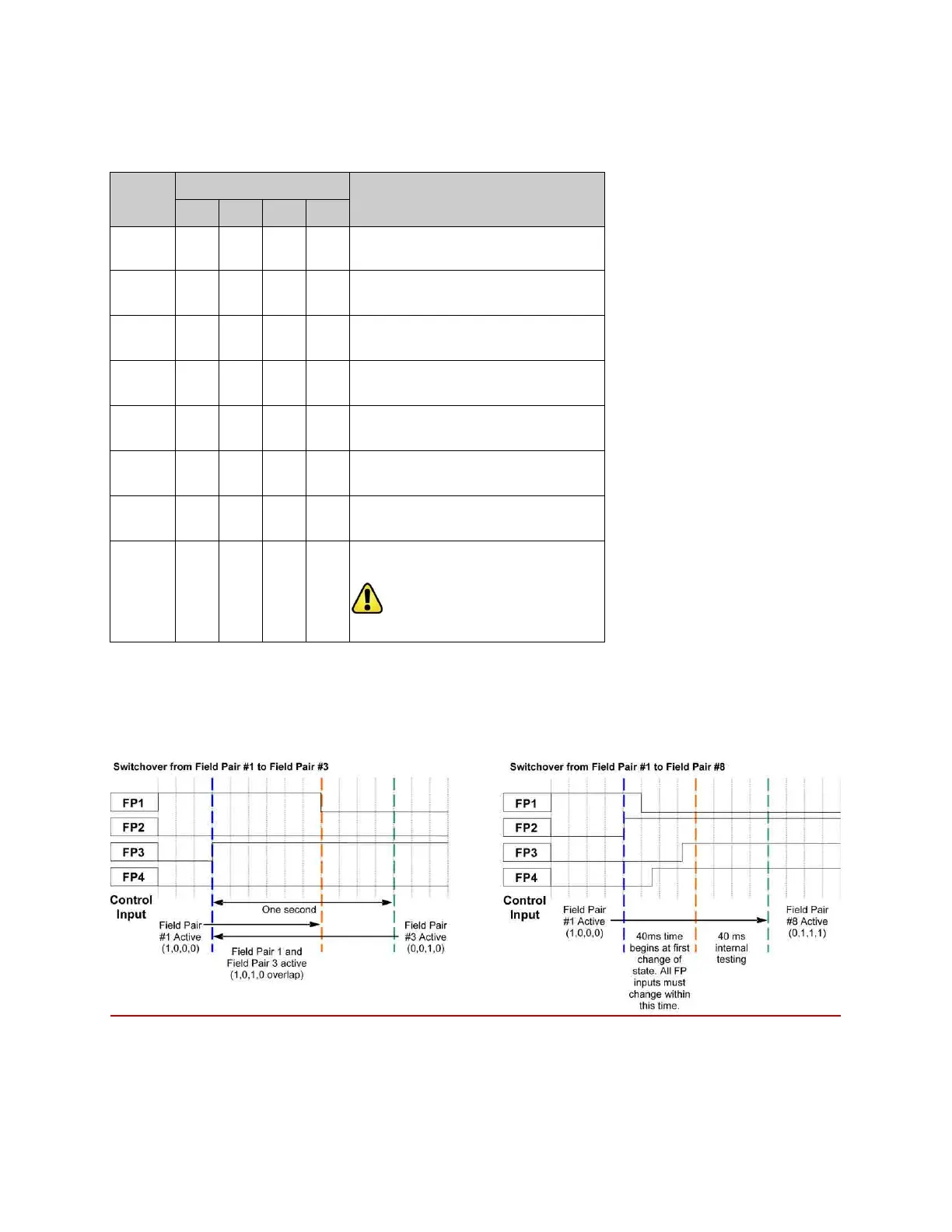
Table 1. Input Logic for Field Pair Control
Field Pair
Control Input Wire
Description
FP1
FP2
FP3
FP4
1
1
0
0
0
Field pair 1 is active
2
0
1
0
0
Field pair 2 is active
3
0
0
1
0
Field pair 3 is active
4
0
0
0
1
Field pair 4 is active
5
1
1
1
0
Field pair 5 is active
6
1
1
0
1
Field pair 6 is active
7
1
0
1
1
Field pair 7 is active
8 0 1 1 1
All fields are deactivated
WARNING . . . Scanner outputs remain ON
Key:
Logic 1 = 30V dc max, 16V min
Logic 0 = < 3V dc
Figure 1-9. Example Field Pair Switchover timing diagrams
Buy: www.ValinOnline.com | Phone 844-385-3099 | Email: CustomerService@valin.com

Table of Contents

Other manuals for Banner AG4 Series

Related product manuals