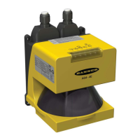
Banner AG4 Series Safety Laser Scanner
Dpf Considerations
Vertical Protective Field Applications (Normal Approach)
For Detection Capability (Resolution), where d ≤ 64 mm (2.5"), the formula for Dpf is:
Dpf = 3.4 x (d – 7 mm)
or
Dpf = 3.4 x (d - 0.275")
where d = the Scanner’s Detection Capability (Resolution)
For Detection Capability (Resolution) d > 64 mm (2.5"), Dpf is 900 mm (36")
WARNING . . . DETERMINE CORRECT STOP TIME
Stop time (T) must include the response time of all devices or controls that react to stop the machine. If all devices are not included, the
calculated Safety distance (S) will be too short. This can lead to serious bodily injury or death. Be sure to include the stop time of all relevant
devices and controls in the calculations.
WARNING . . . PROPER SAFETY DISTANCE
The Protective Field must be located far enough from the nearest hazard such that an individual cannot reach the hazard before
cessation of hazardous motion or situation. Failure to establish and maintain the minimum safety distance could result in serious
bodily injury or death.
Table 4. Vertical Protective Field Applications (Normal Approach)
Detection Capability (Resolution)
d
Horizontal Protective Field Applications (parallel approach)
Dpf = 1200 mm (48")
Note: See Section 3.3.3 for information on allowable Protective Field height, versus resolution.
Scanner-Specific Additional Distance Factors
Two Scanner-specific factors must be considered when calculating the Minimum Safety distance: Z
SM
& Z
refl
Z
SM
Measurement Tolerance Factor
Z
SM
is the additional distance needed to account for distance measurement error. The value for Z
SM
is a function of the
distance from the Scanner (the rotary mirror’s center point) to the furthest point of the Protective Field measured along
the radial (RG).
For Vertical Protective Fields (normal approach): Z
SM
= 0
For Horizontal Protective Fields (parallel approach):
Z
SM
= 83 mm (3.3‖) for Protective Fields RG < 3500 mm (138")
Z
SM
= 100 mm (4‖) for Protective Fields RG ≥ 3500 mm (138")
Z
refl
Retro Reflector Factor
Buy: www.ValinOnline.com | Phone 844-385-3099 | Email: CustomerService@valin.com

 Loading...