Banner AG4 Series Safety Laser Scanner
Notes: The above formula is derived from ISO 13855 (2002).
1. If S is greater than 500 mm, then K = 1600 mm/sec can be used instead of the 2000 mm/sec speed, however, if the 1600
mm/sec value is used, then S can never be less than 500 mm.
2. T is the time from the actuation of the sensing function to the machine's assuming a safe condition, comprising a minimum of
two phases:
T = t1 + t2
Where:
t1 is the maximum time between the actuation of the sensing function and the output signal switching devices (OSSDs) being
in the OFF state. This is the response time of the Scanner.
t2 is the maximum response time of the machine, i.e. the time required to stop the machine or remove the risks after
receiving the output signal from the protective equipment. t2 is influenced by temperature, switching time of valves, ageing of
components, and other factors. t2 is usually measured by a stop-time measuring device. If the machine manufacturer’s
specified stop time is used, add at least 20% to allow for possible clutch/brake system deterioration. This
measurement must take into account the slower of the two MPCE channels, and the response time of all devices or controls
that react to stop the machine (e.g., UM-FA-9A safety module). See Notice Regarding MPCEs in Section 3.4.3. If all
devices are not included, the calculated safety distance (Ds) will be too short and serious injury could result.
3. Consideration for Adjacent Scanners. When adjacent Scanners share the same detection plane and have an
unobstructed view of each other, an additional 40 ms must be added to the response times of both Scanners. If the
adjacent scanners’ detection planes are shielded (therefore no clear line of sight between sensors) or there is at least a 100
mm (4") detection plane offset, then the 40 ms addition is not required.
Distance Adjustment C, Based on the Possible Field Intrusion
Vertical Protective Field Applications (Normal Approach)
For Resolutions d ≤ 40 mm (1.6"), the formula for C is:
C = 8 x (d – 14 mm) or C = 8 x (d - 0.55")
where
d = the Scanner’s Detection Capability (Resolution).
For resolutions 40 mm < d ≤ 70 mm (1.6" < d ≤ 2.8"):
C = 850 mm (34").
For resolutions greater than 70 mm (2.8"), other standards may require:
C = 1200 mm (48") or more.
NOTE: C can never be less than 0 (zero).
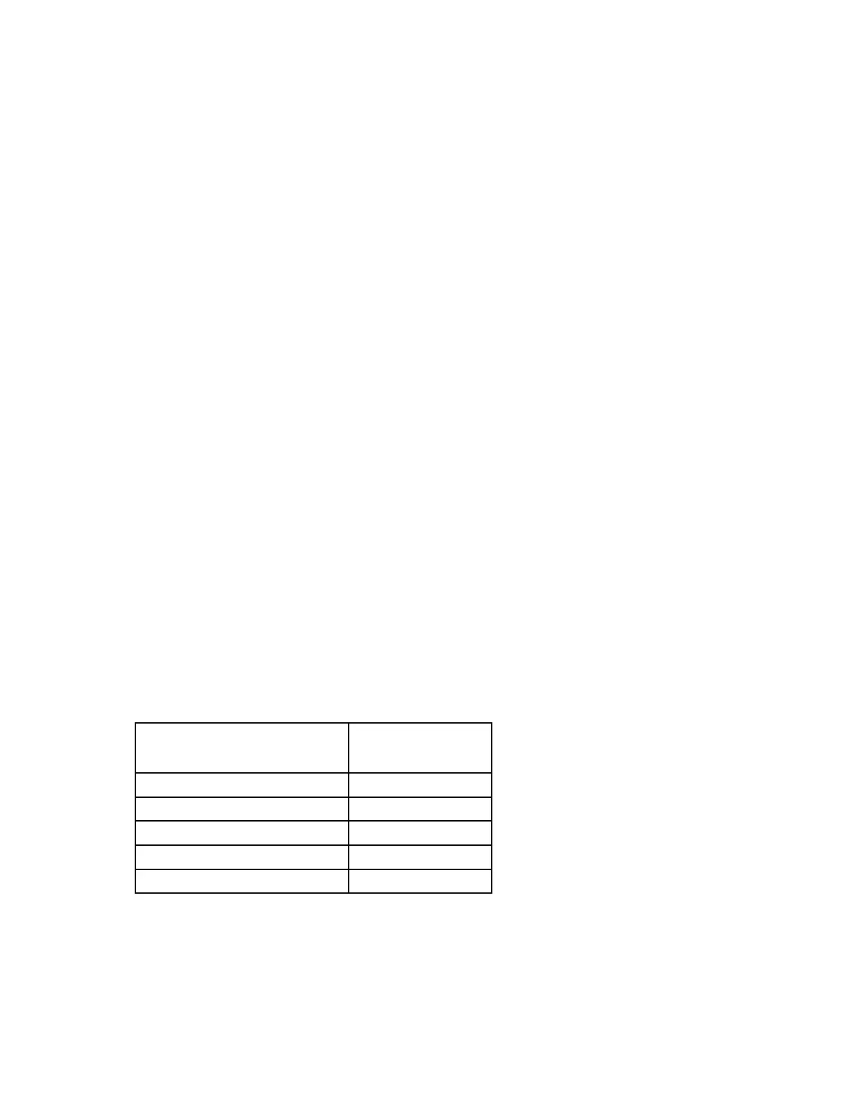
Table 5. Vertical Protective Field Applications (Normal Approach)
Detection Capability (Resolution)
d
Horizontal Protective Field Applications (Parallel Approach)
C = 1200 mm – (0.4 x H) or C = 48" – (0.4 x H)
where H is the distance of the Protective Field above the floor or walking surface (1000 mm max.), see Section
3.1.3 for more information. C can never be less that 850 mm (34").
Buy: www.ValinOnline.com | Phone 844-385-3099 | Email: CustomerService@valin.com

 Loading...

