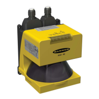
Banner AG4 Series Safety Laser Scanner
D
SD
= [V
MAX
x (T
S
+ T
R
)] + D
B
where:
D
SD
= Stopping distance in mm
V
MAX
= the maximum velocity as stated by the manufacturer of the mobile vehicle
T
S
= maximum stop time (in seconds) of the mobile vehicle (see note 1 below)
T
R
= maximum response time (in seconds) of the Scanner (see note 2 below)
D
B
= Braking Distance at full load and speed as stated by the manufacturer of the mobile
vehicle and other environmental factors (see note 3 below)
Notes
1. T
S
for the mobile vehicle should be supplied by its manufacturer. T
S
must include the response time of all devices or controls
that react to stop the vehicle (e.g., UM-FA-9A Safety Module), which are added to determine the total time to cause
braking/stopping. If all devices are not included, the calculated distance (D
SD
) will be too short and serious injury could result.
2. Consideration for Adjacent Scanners. When adjacent Scanners share the same detection plane and have an unobstructed
view of each other, an additional 40 ms time must be added to the response times of both Scanners. If the adjacent detection
planes are shielded so that there is no clear line of sight between Scanners or the detection planes are offset by at least 100
mm (4"), then the 40 ms addition is not required.
3. Braking Distance (D
B
) should incorporate factors such as brake deterioration and environmental factors that can impact
braking (such as loose dirt/gravel, wet/moisture, icing, etc.) which can add 10% or more to the manufacturer’s stated
distance. It should be noted that braking distance is not a linear function; it increases by a square function as velocity
increases.
Additional Distance Factors (Z) Specific for Mobile Applications
For mobile applications, two additional factors must be considered: Z
SM
and
Z
refl
.
Z
SM
Measurement Tolerance Factor
Z
SM
is the additional distance needed to account for distance measurement error. The value for Z
SM
is a
function of the distance from the Scanner (rotary mirror’s center point) to the furthest point of the Protective
Field, measured along the radial (RG).
For Horizontal Protective Fields (parallel approach):
Z
SM
= 83 mm (3.3") for Protective Fields RG < 3500 mm (138 ")
Z
SM
= 100 mm (4") for Protective Fields RG ≥ 3500 mm (138")
Z
refl
Retro Reflector Factor
Z
refl
is the additional distance needed to account for error due to reflections from retro-reflective or shiny surfaces
that are present in the scanning plane.
No retro-reflectors: Z
refl
= 0
Retro-reflectors located within the scanning plane of the Protective Field: Z
refl
= 100 mm (4")
Z
F
Mobile Vehicle (AGV) Ground Clearance
The additional distance Z
F
is required if the mobile vehicle does not have sufficient ground clearance (H
F
) such
that there is no space under the vehicle or Scanner for the tips of feet. If the wheels are mounted near the side
wall, always add an additional distance Z
F
≥ 150 mm; otherwise Z
F
is determined according to Figure 3-14.
Buy: www.ValinOnline.com | Phone 844-385-3099 | Email: CustomerService@valin.com

 Loading...