EasyManuals Logo

Banner AG4 Series User Manual

Banner AG4 Series
94 pages
To Next Page IconTo Next Page
To Previous Page IconTo Previous Page
Page #73 background imageLoading...
Page #73 background image
Banner AG4 Series Safety Laser Scanner
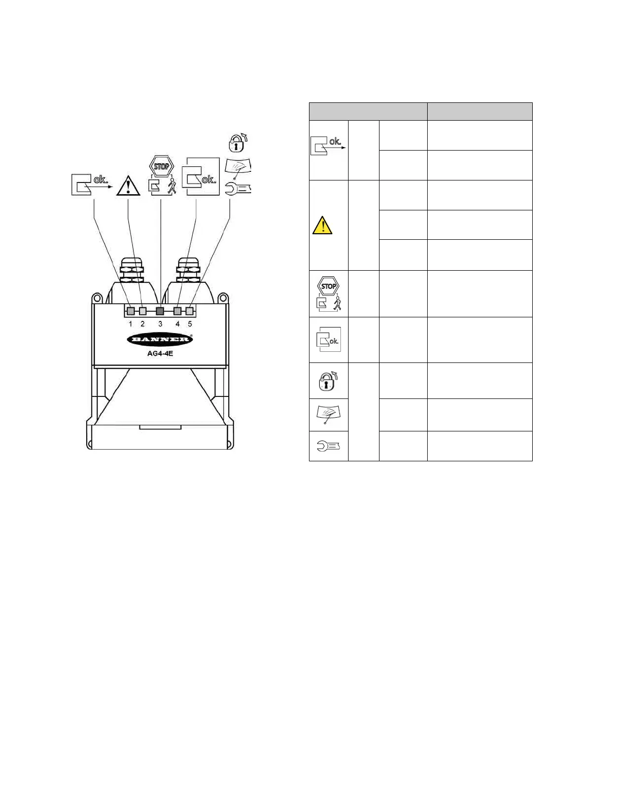
Five LEDs on the housing front show the Scanner's operating status.
LED Diagnostic Key
LED
Meaning
1, green
ON
Sensor function is active; the
active Protective Field is clear.
Flashes @
2 Hz
Fault on the Field Pair control
inputs.
2, yellow
ON
Active Warning Field is
interrupted.
Flashes @
2 Hz
Front screen is dirty.
Flashes @
4 Hz
ConfigPlug configuration is not
compatible with the Scanner.
3, red
ON
Safety outputs or switching
function (OSSD 1 and 2) are
switched off.
4, green
ON
Safety outputs or switching
function (OSSD 1 and 2) are
switched on.
5, yellow
ON
Start/restart interlock is active.
Flashes @
2 Hz
Front screen is dirty.
Flashes @
4 Hz
Fault
Figure 5-1. Status LEDs
Buy: www.ValinOnline.com | Phone 844-385-3099 | Email: CustomerService@valin.com

Table of Contents

Other manuals for Banner AG4 Series

Questions and Answers:

Question and Answer IconNeed help?

Do you have a question about the Banner AG4 Series and is the answer not in the manual?

Banner AG4 Series Specifications

General IconGeneral
BrandBanner
ModelAG4 Series
CategoryScanner
LanguageEnglish

Related product manuals