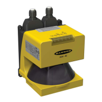
Banner AG4 Series Safety Laser Scanner
8. Observe the Status indicators and the Diagnostic Display:
Lockout: LED #5 flashes at a 4Hz rate (other LEDs may also be ON or flashing depending on the fault,
see Section 5 and Table 10).
Protective Field interrupted: LED #2 (Yellow) and LED #3 (Red) are ON
Protective Field Clear and OSSDs ON: LED #1 (Green) and LED #4 (Green) are ON
Start/Restart Interlock (OSSDs OFF, waiting for Reset): LED #1 (Green), LED #3 (Red), and LED #5
(Yellow) are ON.
9. An interrupted Protective Field (PF) condition indicates that one or more objects are being detected within the
active protected Field. To correct this situation, identify the interruption via the AG4Soft ―Measured contour
display‖ operating mode or by observing the area covered by the Protective Field, and then remove all objects
or realign the Scanner per Section 3. If the system is in a Start/Restart Interlock (waiting for Reset) condition,
perform a manual reset.
10. Once the two Green LED indicators are ON, perform the trip test (described in Section 3.4.3) on each of the
configured Protective Fields to verify proper system operation and to detect possible unmonitored areas. Verify
that if the Protective Field boundary is identified (i.e., marked on the floor), that it matches the corresponding
Protective Field. Do not continue until the Scanner System passes the trip test. Do not expose any
individual to any hazard during the following checks.
11. Apply power to the guarded machine and verify that the machine does not start up. Interrupt the Protective
Field with the appropriate test piece (whose size matches the configured resolution) and verify that it is not
possible for the guarded machine to be put into motion while the Protective Field is interrupted. Repeat for
each configured Protective Field.
12. Initiate the machine cycle or motion of the guarded machine or mobile vehicle. While it is moving, use the
appropriate test piece to interrupt the Protective Field. Do not attempt to insert the test piece into the
dangerous parts of the machine or directly in the path of the moving vehicle. Upon interrupting the
Protective Field (at any point), verify that:
For stationary applications: The dangerous parts of the machine come to a stop with no apparent delay.
Remove the test piece from the Protective Field; verify that the machine does not automatically
restart, and that the initiation device(s) must be engaged to restart the machine.
For mobile applications: The vehicle stops within the identified/predetermined distance. Remove the
test piece from the Protective Field; verify that the vehicle does not unintentionally restart, and, if
required, that the initiation device(s) must be engaged to restart the mobile vehicle. This must be
accomplished at numerous points along the entire route (i.e., testing each of the Field Pairs in the
configuration).
13. Remove electrical power to the Scanner. Verify that both OSSD outputs immediately turn OFF and the
machine is not capable of starting until power is re-applied to the Scanner.
14. Test the machine stopping response time, using an instrument designed for that purpose, to verify that it is the
same or less than the overall system response time specified by the machine manufacturer. (A Banner
Applications Engineer can recommend a suitable instrument.)
WARNING . . . BEFORE APPLYING POWER TO THE MACHINE
Verify that the guarded area is clear of personnel and unwanted materials (such as tools) before applying power to the guarded machine. Failure to
do so could result in serious bodily injury or death.
WARNING . . . IF TRIP TEST INDICATES A PROBLEM
If the Scanner does not respond properly to the trip test, do not attempt to use the system. If this occurs, the Scanner cannot be relied on to stop
dangerous machine motion when a person or object enters the Protective Field. Serious bodily injury or death could result.
Buy: www.ValinOnline.com | Phone 844-385-3099 | Email: CustomerService@valin.com

 Loading...