1. Write the number 10001 as a 16-bit integer into the Command ID register.
2. Toggle the Command bit from 0 to 1 (bit 15 in the Input Bits/Input Coil Bits register).
3. Wait for the Command ACK flag to go from 0 to 1 (bit 15 in the Input Bits ACK/Input Coil Bits ACK register).
4. Verify that the Execution Error flag is not set (that is, the value should be 0). This is bit 15 in the Output Bits/Status
Coil Bits register. If the value is 1, read the Error Code register for more information.
5. Task Complete. Toggle the Command bit back to 0 (bit 15 in the Input Bits/Input Coil Bits register). Read the current
Trigger Mode value in the Command Response Int16 register.
iVu BCR model Trigger Mode Int16 value
TG/Color/Color, BCR External 1
TG/Color Internal 2
TG/Color Free Run 3
TG/Color, BCR Industrial Ethernet Only 10
TG/Color, BCR Command 20
BCR Continuous Scan 5
BCR External Gated 4
Set the desired Trigger Mode for the iVu BCR.
1. Write the number 1 as a 16-bit integer into the Command ID register.
2. Write the desired Trigger Mode's Int16 value from the table above into the Command Parameter Int16 register.
3. Toggle the Command bit from 0 to 1 (bit 15 in the Input Bits/Input Coil Bits register).
4. Wait for the Command ACK
flag to go from 0 to 1 (bit 15 in the Input Bits ACK/Input Coil Bits ACK register).
5. Verify that the Execution Error
flag is not set (that is, the value should be 0). This is bit 15 in the Output Bits/Status
Coil Bits register. If the value is 1, read the Error Code register for more information.
6. Task Complete. Toggle the Command bit back to 0 (bit 15 in the Input Bits/Input Coil Bits register).
Set New Barcode Compare String
This procedure assumes that the Data Compare feature is enabled (found in the Inspection menu for the iVu Plus BCR).
1. Write the number 11001 as a 16-bit integer into the Command ID register.
2. Fill in the Command Parameters String registers with the ASCII data to be used as the new barcode compare string.
3. Write a 32-bit integer value equal to the number of ASCII characters present in the new barcode compare string
data into the Command Parameter String Length register.
4. Toggle the Command bit from 0 to 1 (bit 15 in the Input Bits/Input Coil Bits register).
5. Wait for the Command ACK
flag to go from 0 to 1 (bit 15 in the Input Bits ACK/Input Coil Bits ACK register).
6. Verify that the Execution Error flag is not set (that is, the value should be 0). This is bit 15 in the Output Bits/Status
Coil Bits register. If the value is 1, read the Error Code register for more information.
7. Task Complete. Toggle the Command bit back to 0 (bit 15 in the Input Bits/Input Coil Bits register). The new
barcode compare string will be utilized for the next inspection.
Get/Set Exposure Time
Get the current Exposure Time from the iVu BCR.
1. Write the number 10052 as a 16-bit integer into the Command ID register.
2. Toggle the Command bit from 0 to 1 (bit 15 in the Input Bits/Input Coil Bits register).
3. Wait for the Command ACK
flag to go from 0 to 1 (bit 15 in the Input Bits ACK/Input Coil Bits ACK register).
4. Verify that the Execution Error
flag is not set (that is, the value should be 0). This is bit 15 in the Output Bits/Status
Coil Bits register. If the value is 1, read the Error Code register for more information.
5. Task Complete. Toggle the Command bit back to 0 (bit 15 in the Input Bits/Input Coil Bits register). Read the current
Exposure Time value (in microseconds) in the Command Response Int32 register.
Set the desired Exposure Time for the iVu BCR.
1. Write the number 52 as a 16-bit integer into the Command ID register.
2. Write the desired Exposure Time (in microseconds) as a 32-bit integer value into the Command Parameter Int32
register. The minimum acceptable value is 117 µsec and the maximum value is 1,000,000 µsec.
3. Toggle the Command bit from 0 to 1 (bit 15 in the Input Bits/Input Coil Bits register).
4. Wait for the Command ACK
flag to go from 0 to 1 (bit 15 in the Input Bits ACK/Input Coil Bits ACK register).
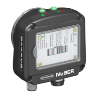
iVu Plus BCR Gen2 Series Sensor
180 www.bannerengineering.com - Tel: + 1 888 373 6767

 Loading...
