Note:
Table 5: Required iVu Input Signal Voltage
ON OFF
NPN < 2 V dc +10 V dc to 30 V dc
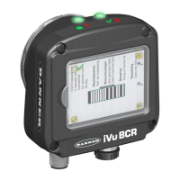
Note: If the device used to trigger or remote teach the iVu BCR is a sinking device, these are the options
regarding the use of a pull-up resistor:
Option 1: Put a pull-up resistor, rated approximately 1 kΩ, between the device's positive (+) voltage and
the device's input as shown below.
Trigger Input
Remote Teach Input
iVu
Pullup Resistor
1k ohm
NPN
VCC
Sinking
Option 2: Enable the Input Pullup. Go to iVu BCR Main Menu > System > Discrete I/O > Input Pullup.
11.10.3 iVu Output Waveforms
Ready
(Pass)
(Fail)
(Pass)
(Pass) (Fail) (Pass)
Function
Strobe Out
(Configure as External
& Expose Based)
Outputs 1,2, and 3
(Set as Active Pass)
Outputs 1, 2, and 3
(Set as Active Fail)
Figure 52. PNP Outputs
iVu Plus BCR Gen2 Series Sensor
www.bannerengineering.com - Tel: + 1 888 373 6767 65

 Loading...
