13.2.2 Setting Up Serial Communications
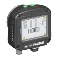
1. Electrically connect the control device and the iVu BCR device. On the iVu BCR, the pins/wire colors used for serial
communications via RS-232 are shown in the following table.
Table 8: iVu BCR RS-232 Connections
Pin # Wire Color Description
10 Light-Blue TX
11 Black Signal Ground
12 Violet RX
2. Configure the port settings (baud rate, data bits, parity, and stop bits) on the iVu BCR to match the settings on the
control device. Go to Main Menu > System > Communications > Serial I/O.
Figure 74. Serial I/O Screen
3. Enable the command channel over the serial connection.
a. Go to Main Menu > System > Communications > Command Channel > Connection and select Serial I/O.
b. Configure the field and end-of-frame delimiters. Go to Main Menu > System > Communications > Command
Channel > Delimiters.
Figure 75. Delimiters Screen
Valid end-of-frame delimiters are: <comma>, <colon>, <semicolon>, <CR>, <CR><LF>, <LF><CR>, or
<ETX>.
c. If you want to trigger the iVu BCR from the control device, set the trigger mode to Command. Go to Main
Menu > Imager > Trigger and select Command from the drop-down list.
Figure 76. Trigger Screen
iVu Plus BCR Gen2 Series Sensor
78 www.bannerengineering.com - Tel: + 1 888 373 6767

 Loading...
