8. Communicator Touch Panel
5
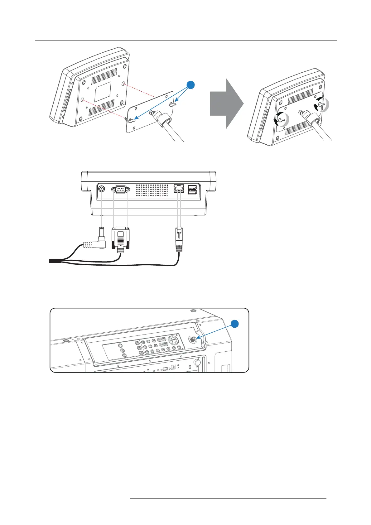
Image 8-6
4. C onnect the DC plug, the RJ45 Ethernet plug and the D-SUB plug of the customized cable into t
heir res pective sockets on the
Touch Panel interface.
Image 8-7
5. C onnect the circular plug of the custom ized cable w ith the circular socket (reference 6 image 8-8) at the right side of the Local
Keypad of the projector.
Caution: To avoid connector dam age, align the pins before you connect the customized cable.
Note: Ensure to tighten the locking nut on the connector.
6
Image 8-8
6. Attach the multi cable to the swivel arm us ing the two Velcro strips.
7. Position the Touch Panel interface in the desired location. See "Repositioning the Touch Panel interface", page 52.
R5977692 DP2K-S SERIES 10/12/2012
51

 Loading...


