4. Physical Installation
Parameter Value
Thread size M12
Length 18mm max 18mm max
Where possible, the projector lens must be positioned exactly perp endicular to the center of the screen. Use
the projector offset (lens shift), rather than physical angling, to correct any off-center positioning.
CAUTION: The po sition and physical securing of the p rojector must be su fficient to prevent it from accidental
or involuntary movement. Pro per secu ring of the projector is the responsibility of the installer and user.
CAUTION: Always use a Rigging Frame when the projector shall be m ounted in other ways than on the feet,
on a flat surface.
The threaded hole in the lower back en d of the p rojector is NOT su itable for lifting or o ther heavy op erations.
Only for adjustment purposes.
Installation and use of the Rigging F rame are described in documen t Rxxxxxx F70 Multifunctional Frame —
Installation M anual.
Mounting on a flat surface
1. Position the projector at the d esired location.
2. Power up the projector.
3. Go to Ma in Menu / Test Patterns and select an internal hatch pattern to display on the screen.
4. Adjust the pr ojector legs until the projected hatch pattern is a level and perfect rectangle.
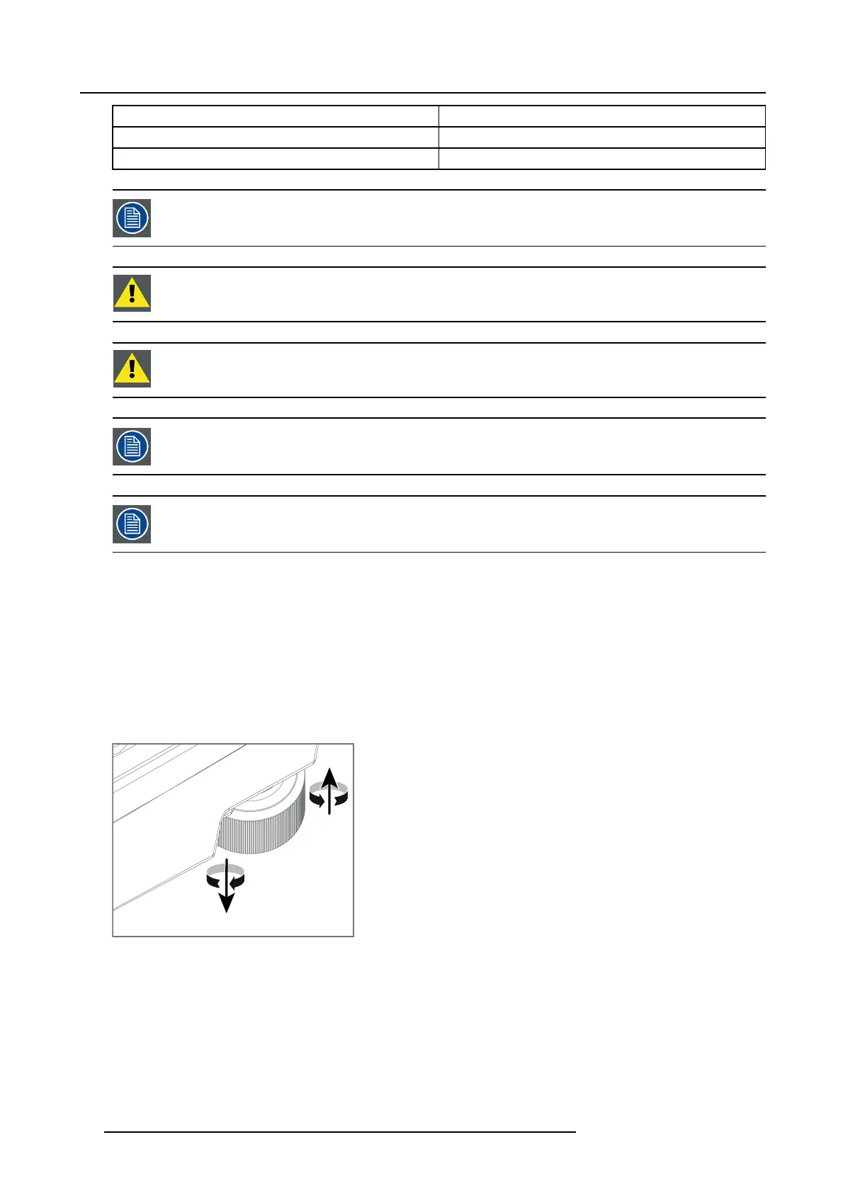
Adjustable feet
Twisting the adjustable feet in either direction, left or right, allows you to fine-a djust the projector position for precise vertical m e-
chanical alignment.
Raise
Lower
Image 4-2
Mounting to a ceiling
1. Install the projector in to an approved ri
gging frame.
2. Install the rigging frame to the desired location.
3. Power up the projector.
4. Go to Main Me nu / Installation / Orientation a nd select the correct orientation for yo ur setup.
5. Go to Ma in Menu / Test Patterns and select an internal hatch pattern to display on the screen.
6. Adjust the position (height and angle) of the rigging frame u n til the projected hatch pattern is a level and perfect rectangle.
34
601–426 F70 SERIES 16/06/2017