5. Lenses & lens holder
Scheimpflug adjustment points
4
1
2
3
d
D
c
C
A
a
B
b
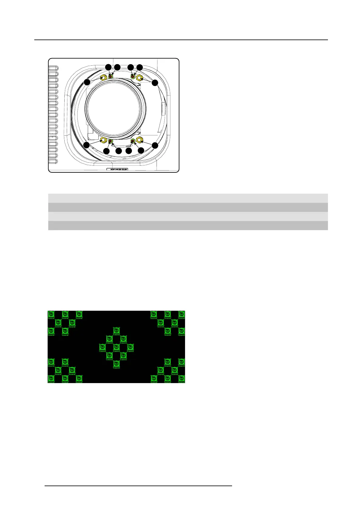
Image 5-22
Scheimpflug adjustments
Indication on drawing Function
4 Locking nut
1, 2 and 3 Scheimpflug adjustment nuts
A, B, C and D Set screws
a, b, c and d lock n uts
1, 2 and 3 ar e adjustment points.
4 is a locking point and NOT us ed during Scheimpflug adjustment.
Necessary tools
• Allenkey3mm
• Nut driver 13 mm
• Nut driver 10 mm
How to adjust
1. Project a gr een focus pattern. For a 4K projector,
use the 4K test pattern. Otherwise, use the 2K test pattern.
Image 5-23
2. L oosen the lock nuts (a, b, c and d). See image 5-22.
3. L oosen the 4 set screws (A, B, C and D) by 1 cm. See image 5-22.
4. Fully loosen lock nut 4 . See image 5-22.
5. Optimize the focus of the projected image as follows:
a) Turn the Scheimpflug adjustment nuts 1, 2 and 3 until the front of the nut is equally aligned w ith the front of the threaded rod.
b) A djust the focus in the center of the screen (F) using the m otorized focus control.
52
R5905067 DPXK-19B/23B/P 17/09/2012
 Loading...