I/O Control AW00011916000
96 Basler scout GigE
8.2.4 Working with Timers
The camera has four timer output signals available: Timer 1, Timer 2, Timer 3, and Timer 4. As
shown in Figure 44, each timer works as follows:
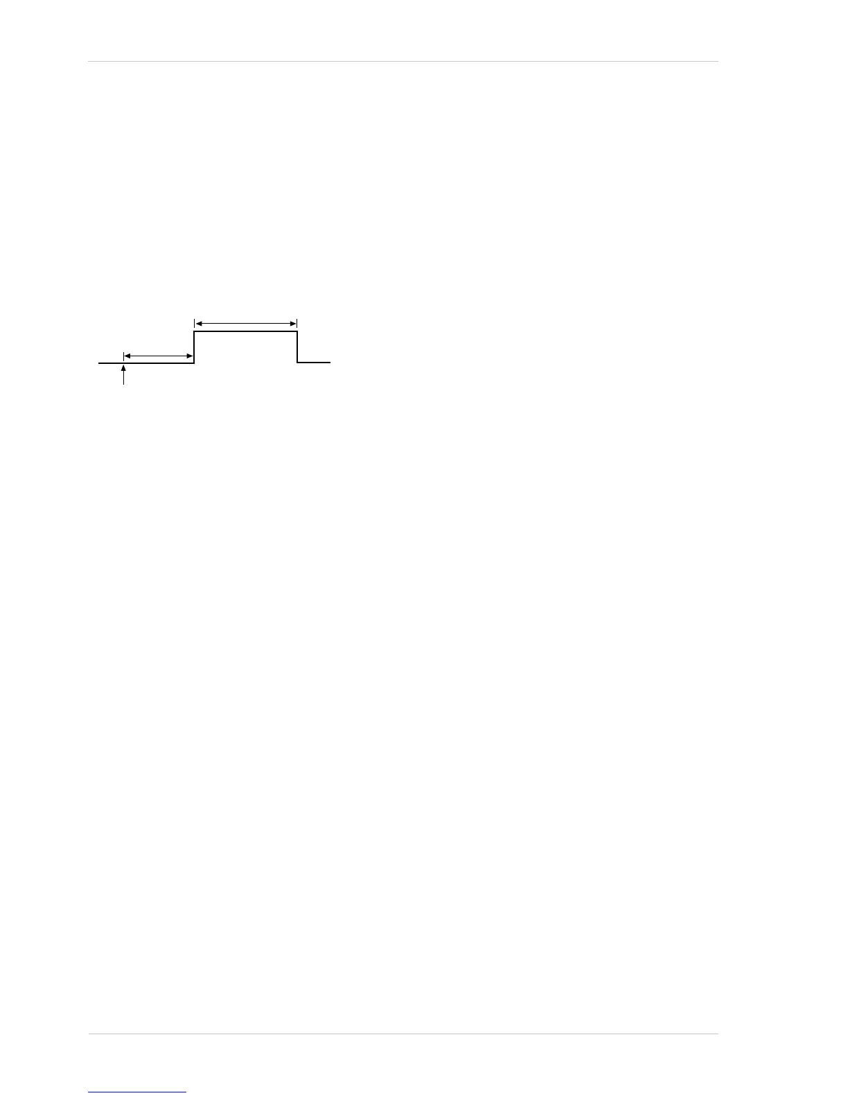
A trigger source event occurs that starts the timer.
A delay period begins to expire.
When the delay expires, the timer signal goes high and a duration period begins to expire.
When the duration period expires, the timer signal goes low.
Fig. 44: Timer Signal
Currently, the only trigger source event available to start the timer is "exposure active". In other
words, you can use exposure start to trigger the start of a timer.
Timer 1 can only be assigned to output line 1. Timer 2 can only be assigned to output line 2. Timer
3 can only be assigned to output line 3. Timer 4 can only be assigned to output line 4.
If you require the timer signal to be high when the timer is triggered and to go low when the delay
expires, simply set the output line to invert.
Timer with Increased Signal Width
The explanations given above assume that the timer is not modified by the Minimum Output Pulse
Width feature.
If the timer us used with the Minimum Output Pulse Width feature and if the set minimum output
signal width is larger than the timer duration setting the Minimum Output Pulse Width feature will
control the output signal width. Accordingly, the timer duration setting will be ignored.
If the set minimum output signal width is smaller than the timer duration setting the Minimum Output
Pulse Width feature will have no effect.
For more information about the Minimum Output Pulse Width feature, see Section 12.12 on
page 304.

 Loading...