BeagleBone Black System
Reference Manual
Page 36 of 108
6.1 Power Section
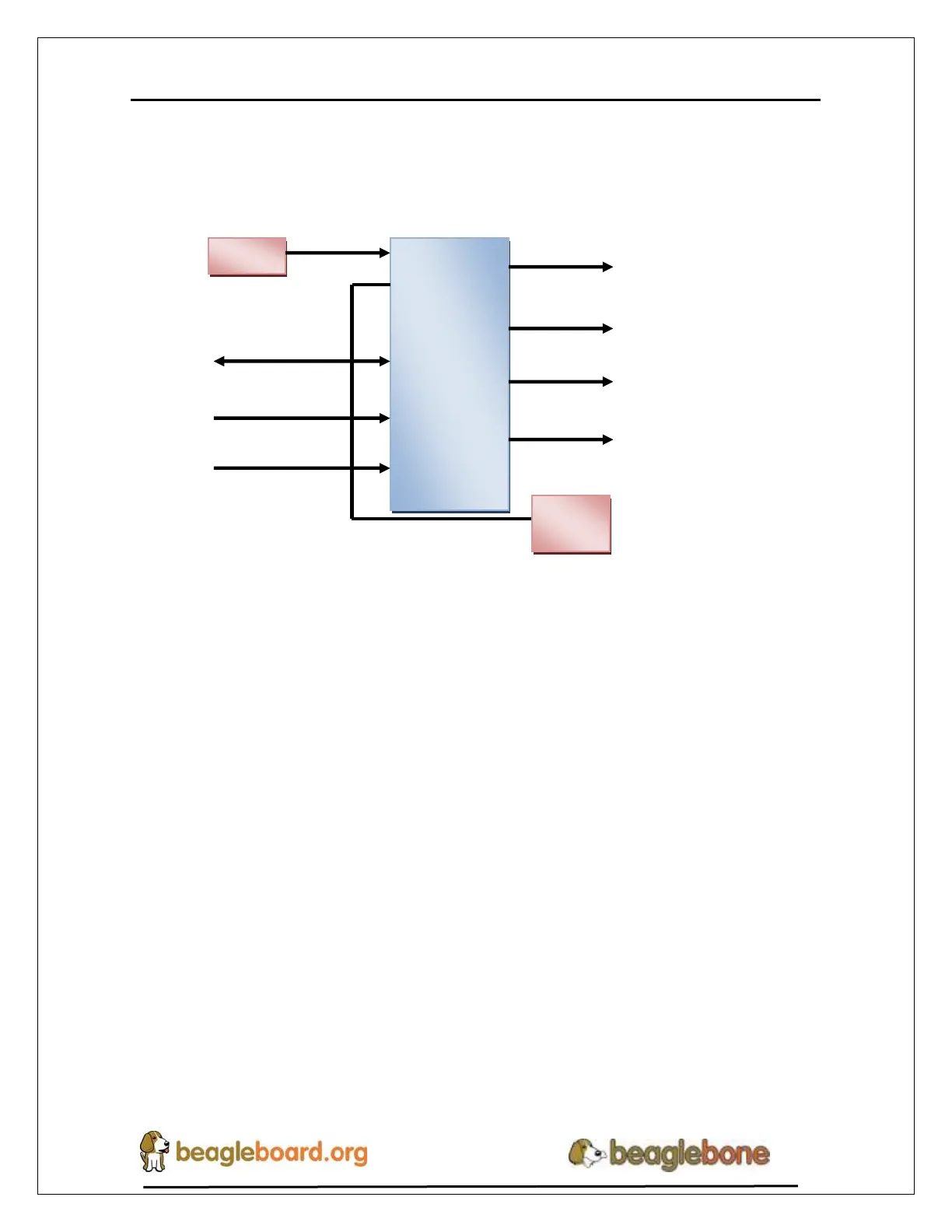
Figure 21 is the high level block diagram of the power section of the board.
Figure 21. High Level Power Block Diagram
This section describes the power section of the design and all the functions performed by the
TPS65217C.
6.1.1 TPS65217C PMIC
The main Power Management IC (PMIC) in the system is the TPS65217C which is a
single chip power management IC consisting of a linear dual-input power path, three
step-down converters, and four LDOs. The system is supplied by a USB port or DC
adapter. Three high-efficiency 2.25MHz step-down converters are targeted at providing
the core voltage, MPU, and memory voltage for the board.
The step-down converters enter a low power mode at light load for maximum efficiency
across the widest possible range of load currents. For low-noise applications the devices
can be forced into fixed frequency PWM using the I2C interface. The step-down
converters allow the use of small inductors and capacitors to achieve a small footprint
solution size.
LDO1 and LDO2 are intended to support system standby mode. In normal operation,
they can support up to 100mA each. LDO3 and LDO4 can support up to 285mA each.
By default only LDO1 is always ON but any rail can be configured to remain up in
SLEEP state. In particular the DCDC converters can remain up in a low-power PFM
mode to support processor suspend mode. The TPS65217C offers flexible power-up and