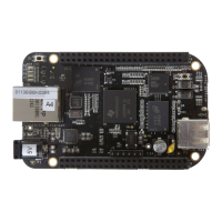
BeagleBone Black System
Reference Manual
Page 7 of 108
Table of Contents
FIGURES ...................................................................................................................................................... 9
TABLES .......................................................................................................................................................11
1.0 INTRODUCTION..............................................................................................................................12
2.0 CHANGE HISTORY .........................................................................................................................12
2.1 DOCUMENT CHANGE HISTORY ........................................................................................................12
2.2 BOARD CHANGES .............................................................................................................................12
2.2.1 Rev A5B .................................................................................................................................12
3.0 CONNECTING UP YOUR BEAGLEBONE BLACK ...................................................................13
3.1 WHAT’S IN THE BOX ........................................................................................................................13
3.2 MAIN CONNECTION SCENARIOS.......................................................................................................14
3.3 TETHERED TO A PC .........................................................................................................................14
3.3.1 Connect the Cable to the Board .............................................................................................15
3.3.2 Accessing the Board as a Storage Drive................................................................................16
3.4 STANDALONE W/DISPLAY AND KEYBOARD/MOUSE ........................................................................17
3.4.1 Required Accessories .............................................................................................................17
3.4.2 Connecting Up the Board ......................................................................................................18
5. Apply Power ...............................................................................................................................20
4.0 BEAGLEBONE BLACK OVERVIEW ...........................................................................................24
4.1 BEAGLEBONE COMPATIBILITY ........................................................................................................25
4.2 BEAGLEBONE BLACK FEATURES AND SPECIFICATION.....................................................................26
4.3 BOARD COMPONENT LOCATIONS.....................................................................................................27
4.3.1 Connectors, LEDs, and Switches ...........................................................................................27
4.3.2 Key Components ....................................................................................................................28
5.0 BEAGLEBONE BLACK HIGH LEVEL SPECIFICATION ........................................................29
5.1 BLOCK DIAGRAM .............................................................................................................................29
5.2 PROCESSOR ......................................................................................................................................30
5.3 MEMORY..........................................................................................................................................30
5.3.1 512MB DDR3L ......................................................................................................................30
5.3.2 32KB EEPROM .....................................................................................................................30
5.3.3 2GB Embedded MMC ............................................................................................................30
5.3.4 MicroSD Connector ...............................................................................................................30
5.3.5 Boot Modes ............................................................................................................................31
5.4 POWER MANAGEMENT.....................................................................................................................31
5.5 PC USB INTERFACE .........................................................................................................................32
5.6 SERIAL DEBUG PORT .......................................................................................................................32
5.7 USB1 HOST PORT ............................................................................................................................32
5.8 POWER SOURCES .............................................................................................................................32
5.9 RESET BUTTON ................................................................................................................................33
5.10 POWER BUTTON ..........................................................................................................................33
5.11 INDICATORS ................................................................................................................................33
5.12 CTI JTAG HEADER .....................................................................................................................33
5.13 HDMI INTERFACE .......................................................................................................................34
5.14 CAPE BOARD SUPPORT................................................................................................................34
6.0 DETAILED HARDWARE DESIGN ...............................................................................................35
6.1 POWER SECTION ..............................................................................................................................36
6.1.1 TPS65217C PMIC .................................................................................................................36
6.1.2 DC Input ................................................................................................................................38