BeagleBone Black System
Reference Manual
Page 57 of 108
6.7 Boot Configuration
The design supports two groups of boot options on the board. The user can switch
between these modes via the Boot button. The primary boot source is the onboard eMMC
device. By holding the Boot button, the user can force the board to boot from the uSD
slot. This enables the eMMC to be overwritten when needed or to just boot an alternate
image. The following sections describe how the boot configuration works.
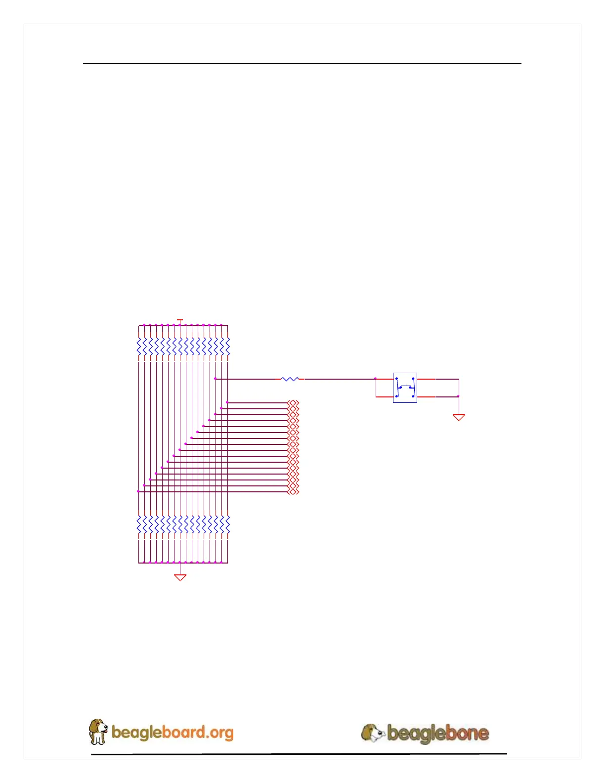
6.7.1 Boot Configuration Design
Figure 35 shows the circuitry that is involved in the boot configuration process. On
power up, these pins are read by the processor to determine the boot order. S2 is used to
change the level of one bit from HI to LO which changes the boot order.
R80100K,1%
R83100K,1%
R84100K,1%
R85100K,1%
R87100K,1%
R86100K,1%
R89100K,1%
R88100K,1%
R82100K,1%
R95100K,1%
uSD BOOT
VDD_3V3A
SYS_BOOT10
SYS_BOOT9
SYS_BOOT8
SYS_BOOT15
SYS_BOOT14
SYS_BOOT13
SYS_BOOT12
SYS_BOOT11
SYS_BOOT4
SYS_BOOT2
SYS_BOOT1
SYS_BOOT0
SYS_BOOT7
SYS_BOOT6
SYS_BOOT5
SYS_BOOT3
DGND
LCD_DATA5
4,10,11
LCD_DATA4
4,10,11
LCD_DATA3
4,10,11
R65100K,1%
LCD_DATA8
4,10,11
LCD_DATA7
4,10,11
LCD_DATA6
4,10,11
LCD_DATA11
4,10,11
LCD_DATA10
4,10,11
LCD_DATA9
4,10,11
LCD_DATA14
4,10,11
LCD_DATA13
4,10,11
LCD_DATA12
4,10,11
LCD_DATA1
4,10,11
LCD_DATA0
4,10,11
LCD_DATA15
4,10,11
LCD_DATA2
4,10,11
R69100K,1%,DNI
R93100K,1%,DNI
R92100K,1%,DNI
S2
KMR231GLFS
1 3
2 4
R68100K,1%
R91100K,1%,DNI
DGND
R90100K,1%,DNI
R64100K,1%,DNI
R75 100
R70100K,1%,DNI
R63100K,1%,DNI
R56100K,1%
R67100K,1%
R66100K,1%
R62100K,1%,DNI
R61100K,1%,DNI
R60100K,1%,DNI
R94100K,1%
R59100K,1%,DNI
R58100K,1%,DNI
R57100K,1%,DNI
R81100K,1%,DNI
R55100K,1%,DNI
Figure 35. Processor Boot Configuration Design
It is possible to override these setting via the expansion headers. But be careful not to add
too much load such that it could interfere with the operation of the HDMI interface or
LCD panels. If you choose to override these settings, it is strongly recommended that you
gate these signals with the SYS_RESETn signal. This insures that after coming out of
reset these signals are removed from the expansion pins.