BeagleBone Black System
Reference Manual
Page 61 of 108
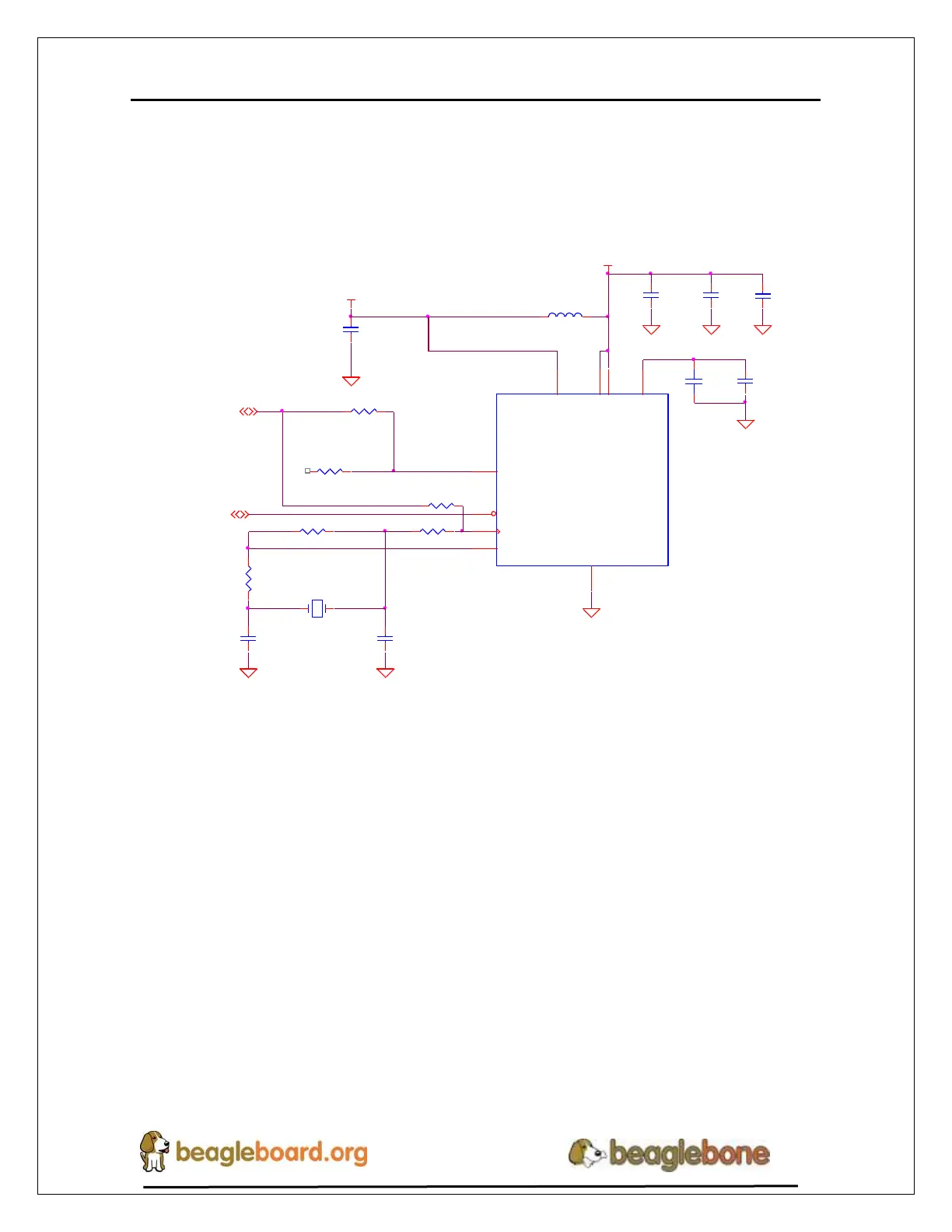
Ethernet PHY Power, Reset, and Clocks
Figure 39 show the power, reset, and lock connections to the LAN8710A PHY. Each of
these areas is discussed in more detail in the following sections.
PHY _VDDCR
PHY _XTAL2
PHY _XTAL1
PHY X
REFCLKO
C135
0.1uf ,6.3V
C131
0.1uf ,6.3V
C132
0.1uf ,6.3V
R131 100,1%
R142 0,1%
FB4150OHM800mA
1 2
R143
10,1%
C143
30pF,50V
U14
LAN8710A
nRST
19
XTAL1/CLKIN
5
XTAL2
4
GND_EP
33
VDDIO
12
VDD1A
27
VDD2A
1
VDDCR
6
RXCLK/PHY AD1
7
R140 0,1%,DNI
C134
1uF,10V
C142
30pF,50V
Y3
25.000MHz
XTAL150SMD_125X196
12
C136
470pF,6.3V
R124 10,1%,DNI
R141
1M,1%,DNI
DGND
VDD_PHY A
VDD_3V3B
DGND
DGND
DGNDDGND
DGND
DGND
DGND
SYS_RESETn
3,11
RMII1_REFCLK
4
C133
10uF,10V
RCLKIN
Figure 39. Ethernet PHY, Power, Reset, and Clocks
6.8.2.1 VDD_3V3B Rail
The VDD_3V3B rail is the main power rail for the LAN8710A. It originates at the
VD_3V3B regulator and is the primary rail that supports all of the peripherals on the
board. This rail also supplies the VDDIO rails which set the voltage levels for all of the
I/O signals between the processor and the LAN8710A.
6.8.2.2 VDD_PHYA Rail
A filtered version of VDD_3V3B rail is connected to the VDD rails of the LAN8710 and
the termination resistors on the Ethernet signals. It is labeled as VDD_PHYA. The
filtering inductor helps block transients that may be seen on the VDD_3V3B rail.