BeagleBone Black System
Reference Manual
Page 67 of 108
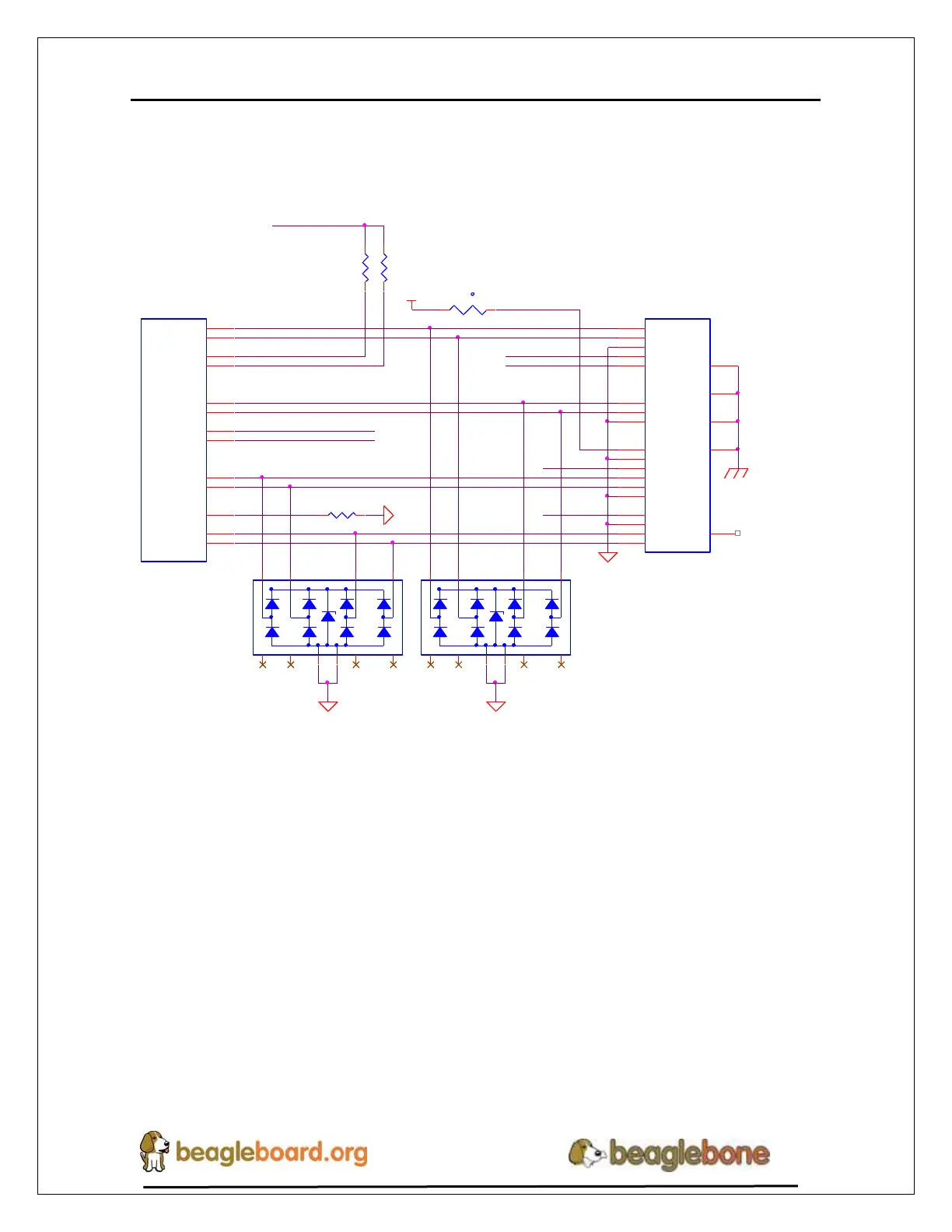
6.9.8 HDMI Connector Interface
Figure 43 shows the design of the interface between the HDMI Framer and the
connector.
HDMI_TX2+
HDMI_TX2-
HDMI_CEC
HDMI_HPD
HDMI_DSDA
HDMI_DSCL
R1461.5K,5%
DVI_+5V
R1471.5K,5%
DVI_+5V
HDMI_DSDA
HDMI_DSCL
HDMI_CEC
HDMI_HPD
R148 10K,1%
DGND
HDMI_SWING
U11
TDA19988
DSCL
33
DSDA
32
HPD
31
CEC
30
TXC+
38
TXC-
37
TX0+
40
TX0-
39
TX1+
43
TX1-
42
TX2+
45
TX2-
44
EXT_SWING
34
3 8
1 2 4 5 D7
IP4283CZ10-TT
3 8
1 2 4 5D6
IP4283CZ10-TT
P6
microHDMI
DAT2+
3
DAT2-
5
DAT2_S
4
DAT1+
6
DAT1_S
7
DAT1-
8
DAT0+
9
DAT0_S
10
DAT0-
11
CLK+
12
CLK-
14
CLK_S
13
CEC
15
NC
2
SCL
17
SDA
18
DDC/CEC GND
16
+5V
19
HPLG
1
MTG1
20
MTG2
21
MTG3
22
MTG4
23
t
RT1
PTC_RXEF010
SYS_5V
DGND
DGNDDGND
HDMI_TX0+
HDMI_TX1-
HDMI_TXC-
HDMI_TXC+
HDMI_TX0-
HDMI_TX1+
Figure 43. Connector Interface Circuitry
The connector for the HDMI interface is a microHDMI. It should be noted that this
connector has a different pinout than the standard or mini HDMI connectors. D6 and D7
are ESD protection devices.