BeagleBone Black System
Reference Manual
Page 38 of 108
6.1.2 DC Input
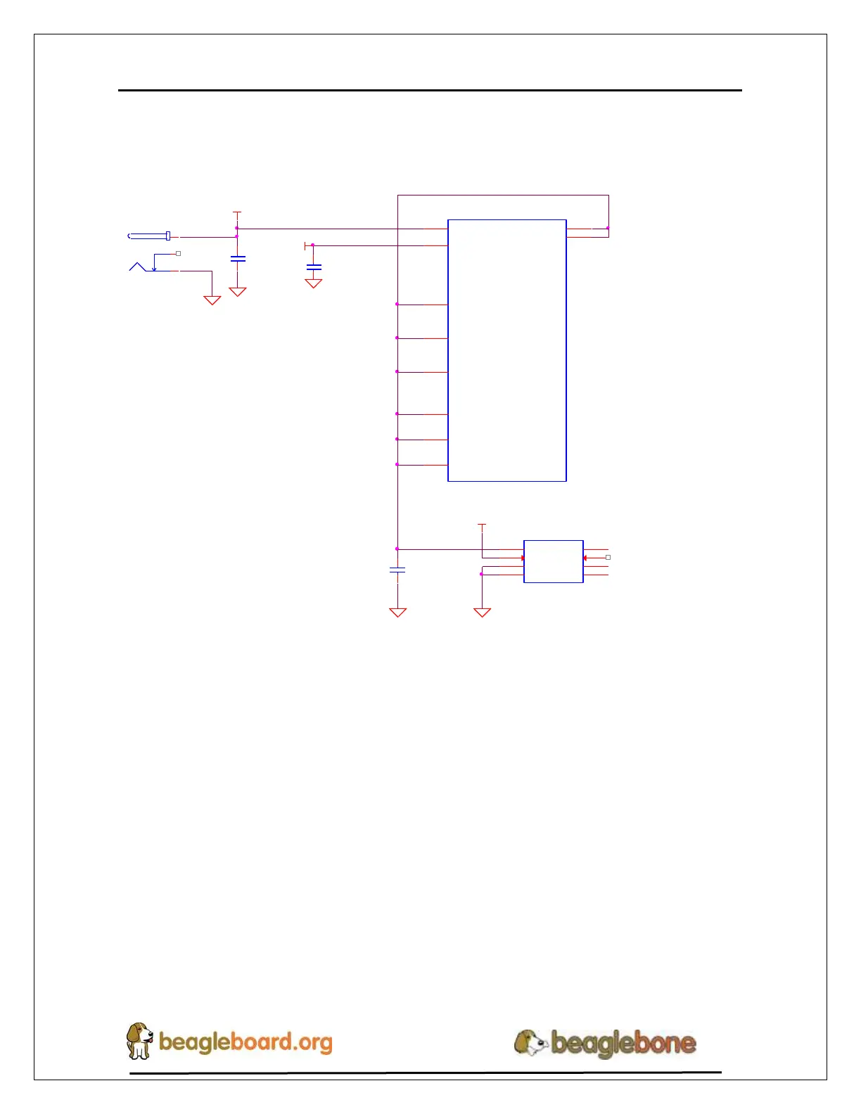
Figure 23 below shows how the DC input is connected to the TPS65217C.
VDD_5V
P1
PJ-200A
1
1
3
3
2
2
DGND
DGND
C1
10uF,10V
C2
10uF,10V
DGND
U2
TPS65217C
AC
10
USB
12
SYS1
7
SYS2
8
VIN_DCDC1
21
VIN_DCDC3
32
VINLDO
2
LDO3_IN
39
VIN_DCDC2
22
LDO4_IN
42
USB_DC
U4
TL5209
IN
2
OUT
3
GND1
5
EN
1
ADJ
4
GND3
6
GND2
7
GND4
8
DGND
VDD_3V3A
DGND
C17
2.2uF,6.3V
Figure 23. TPS65217 DC Connection
A 5VDC supply can be used to provide power to the board. The power supply current
depends on how many and what type of add-on boards are connected to the board. For
typical use, a 5VDC supply rated at 1A should be sufficient. If heavier use of the
expansion headers or USB host port is expected, then a higher current supply will be
required.
The connector used is a 2.1MM center positive x 5.5mm outer barrel. The 5VDC rail is
connected to the expansion header. It is possible to power the board via the expansion
headers from an add-on card. The 5VDC is also available for use by the add-on cards
when the power is supplied by the 5VDC jack on the board.