BeagleBone Black System
Reference Manual
Page 62 of 108
6.8.2.3 PHY_VDDCR Rail
The PHY_VDDCR rail originates inside the LAN8710A. Filter and bypass capacitors
are used to filter the rail. Only circuitry inside the LAN8710A uses this rail.
6.8.2.4 SYS_RESET
The reset of the LAN8710A is controlled via the SYS_RESETn signal, the main board
reset line.
6.8.2.5 Clock Signals
A crystal is used to create the clock for the LAN8710A. The processor uses the
RMII_RXCLK signal to provide the clocking for the data between the processor and the
LAN8710A.
6.8.3 LAN8710A Mode Pins
There are mode pins on the LAN8710A that sets the operational mode for the PHY when
coming out of reset. These signals are also used to communicate between the processor
and the LAN8710A. As a result, these signals can be driven by the processor which can
cause the PHY not to be initiated correctly. To insure that this does not happen, three low
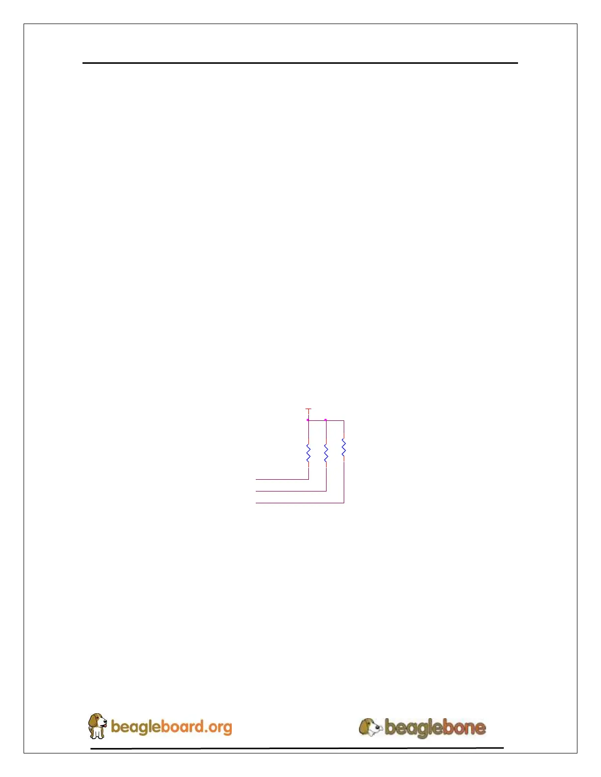
value pull up resistors are used. Figure 40 below shows the three mode pin resistors.
MODE2
RXD1/MODE1
RXD0/MODE0
R1141.5K,1%
R1121.5K,1%
R1131.5K,1%
VDD_3V3B
Figure 40. Ethernet PHY Mode Pins
This will set the mode to be 111, which enables all modes and enables auto-negotiation.
This design