BeagleBone Black System
Reference Manual
Page 56 of 108
connectors. In the BeagleBone Black design, this pin is connected to the MMC0_SDCD
pin for use by the processor. You can also change the pin to GPIO0_6, which is able to
wake up the processor from a sleep mode when an SD card is inserted into the connector.
Pullup resistors are provided on the signals to increase the rise times of the signals to
overcome PCB capacitance.
Power is provided from the VDD_3V3B rail and a 10uf capacitor is provided for
filtering.
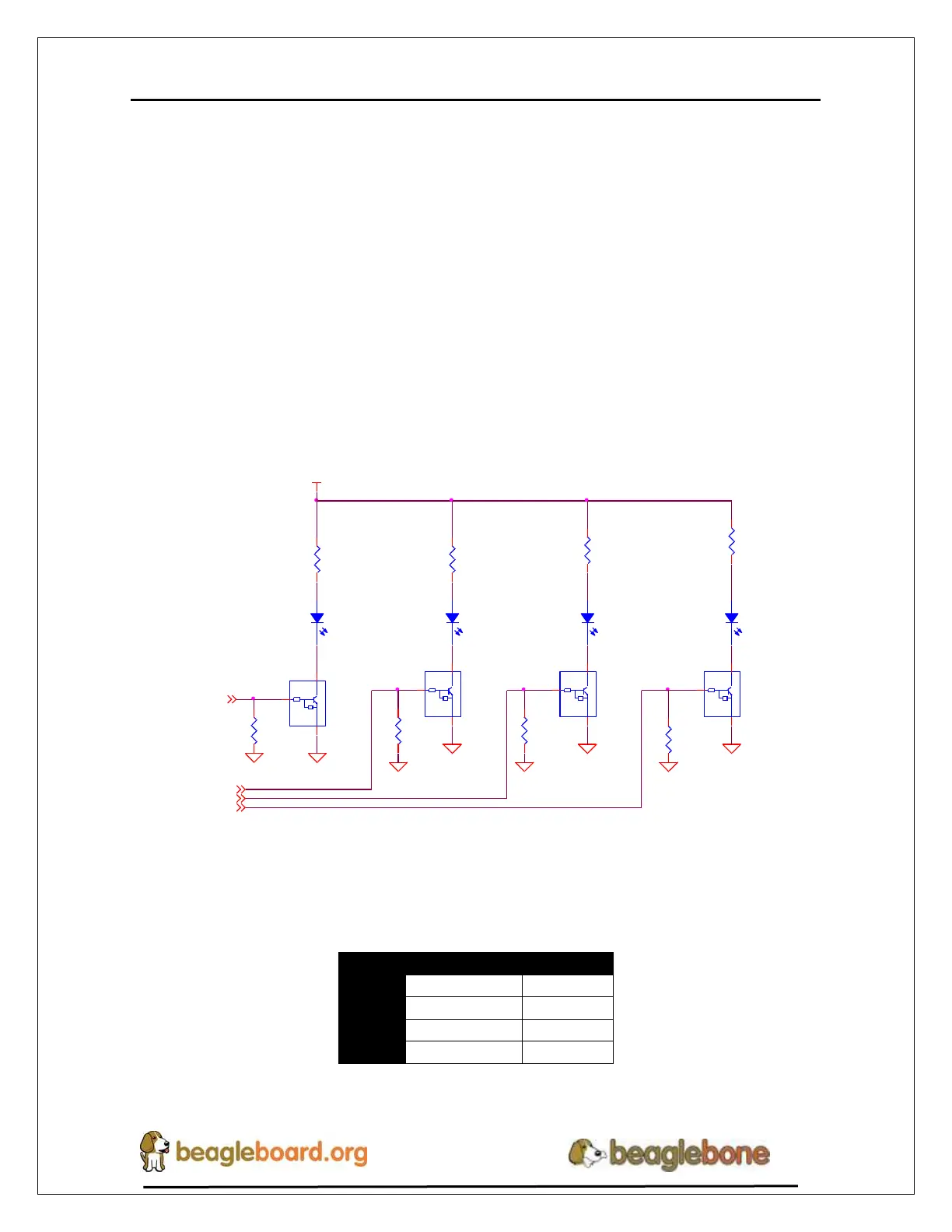
6.6 User LEDs
There are four user LEDs on the BeagleBone Black. These are connected to GPIO pins
on the processor. Figure 34 shows the interfaces for the user LEDs.
R76
100K,1%
R77
100K,1%
D2 LTST-C191TBKT
DGND
DGND
47k
10k
Q1A
DMC56404
1 6
2
47k
10k
Q1B
DMC56404
4 3
5
DGND
DGND
USR1
3
USR0
3
LEDAC
LEDBC
USR0
R73
820,5%
R72
820,5%
LEDAA
LEDBA
SYS_5V
D3 LTST-C191TBKT D4 LTST-C191TBKT D5 LTST-C191TBKT
R78
100K,1% R79
100K,1%
DGND
47k
10k
Q2A
DMC56404
1 6
2
47k
10k
Q2B
DMC56404
4 3
5
DGND
USR2
3
DGNDDGND
USR3
3
USR1
LEDDC
LEDCC
USR3
USR2
R74
820,5%
LEDCA
LEDDA
R71
820,5%
Figure 34. User LEDs
Table 7 shows the signals used to control the four LEDs from the processor.
Table 7. User LED Control Signals/Pins
A logic level of “1” will cause the LEDs to turn on.