131
processor by system firmware so that commands can be issued to configure the DDP ASIC, the analog interface device,
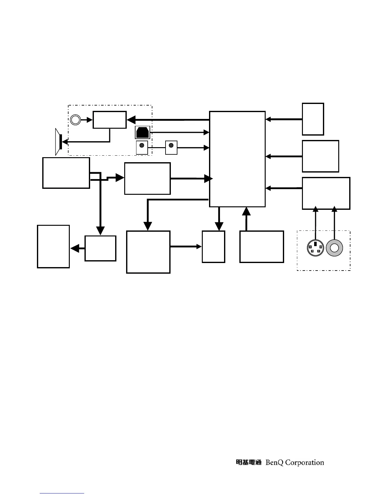
the video decoder, the cooling device, and other system peripheral devices. Please see figure 2.
Figure 2 Main board & Input board BLOCK DIAGRAM
1.2 User Interface Function
(1) Keypad function: There are 9 keypads on top case. Please see Figure 3. MCU does polling on these signals
[KEY8:0] to detect the key pressing action. Each key pressing action will request MCU to execute the specified
program.
(2) Indicator LED function: There are 3 twice color LED on top case. MCU releases the status of program indication
by setting LED signal LED[6:0]. It will show the power status, lamp status, and temperature status.
(3) IR remote function: There are two IR receivers, one is at the front side, and the other one is at back side. The
receiver sensor has 3 legs, pin1 is output, pin2 is ground, and pin3 is VCC (5V). The output pin is pulled high,
and will sink to low when it receives infrared signal coming from remote controller. MCU will decode the signal
and execute related program.
(4) USB function: There is a B type USD terminal for mouse port at back side. MCU supports the universal serial bus
version 1.1 in a slave mode only.
Main Board
A/D converter