EasyManua.ls Logo

BenQ MP611 - Cooling Circuit Operation Theory; Fan Control & DC;DC Board Block Diagram

BenQ MP611
168 pages
Print Icon
To Next Page IconTo Next Page
To Previous Page IconTo Previous Page
Loading...
139
Chapter 4 Cooling Circuit Operation Theory
4.1 Overview
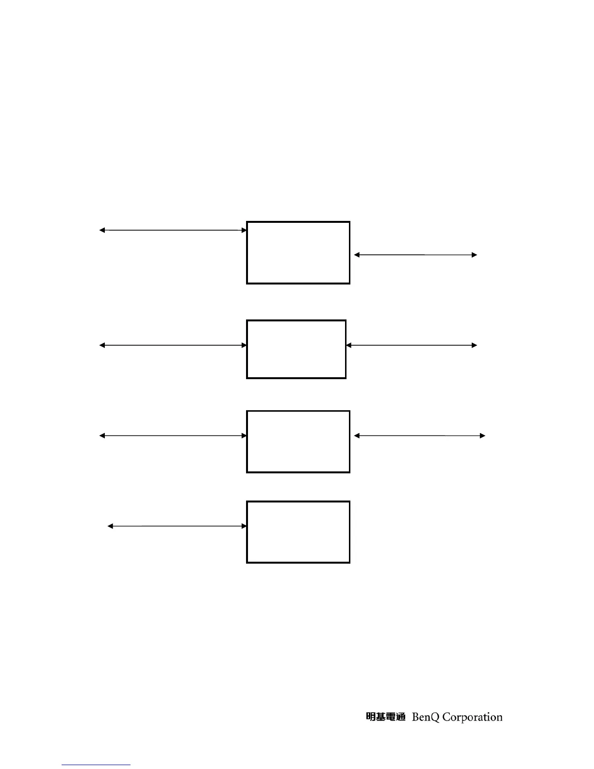
The Projector cooling circuits consist of Fan driver devices, Fans, and Thermal sensors. The cooling purpose is for
protecting System Elements from over heat damage. Please see figure 8. The particular hot spot points are Lamp Tip,
Lamp Burner, DMD Heat-sink, and Lamp Box. There are three fans, blower fan, main fan 1, and main fan 2 for driving
airflow to cool down the system and hot spot point temperature.
Figure 10 Fan Control & DC/DC board BLOCK DIAGRAM
Fan Control & DC/DC Board
DC/DC
To PFC
board
REAR FAN
DRIVER
BLOWER FAN
DRIVER
To Main
board
B+
VCC
V12, VDD
2V5
To Main
board
To Rear
Fan
To Blower
Fan
To Ballast
board
To Thermal
Break/lamp
box sensor
LAMP
CONTROL

Table of Contents

Related product manuals