137
The Projector signal input terminals consist of PC VGA (Component) input, PC VGA output, S-Video input, Video
input, and PC Audio input.
3.2 Graphics Signal Processing
PC VGA (Component) Input: The PC VGA (Component) Inputs consist of PC analog RGB signal, PC HSYNC
signal, PC VSYNC signal, PC EDID/DDC signal, and Component YPBPR signal. RGB signal will be converted to digital
24 bits format and feed for DDP ASIC by an Analog to Digital convert device built on main board. The HSYNC and
VSYNC will be rectified by a high speed Schmitt trigger inverter, and is fed to ADC device. PC DDC signal will link to an
EEPROM built on main board. The EDID function setting data please refer to C212 Software Specification. Component
signal is plugged in by a VGA to RCA convert cable. This signal will be also converted to digital data by ADC device.
Please refer figure 2.
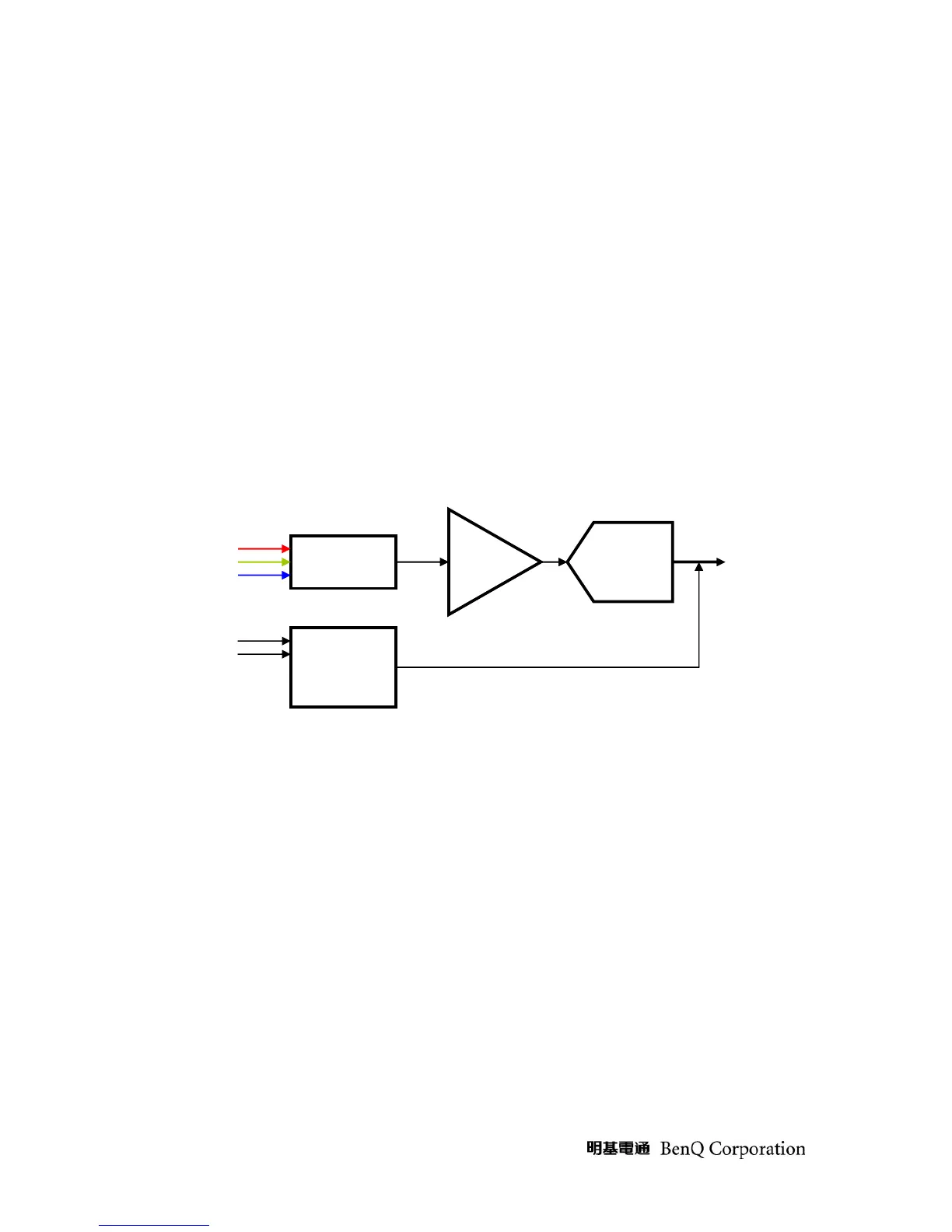
ADC device consists of Analog interface, Sync processing, and Digital interface. The ADC device is the key
component for graphics signal processing. It is a fully integrated solution for capturing analog RGB signals and
digitizing them for display on projector. Please see Figure 8.
CLAMP
Digital RGB 24
bits output
Figure 8 ADC device operation concept
Rin Gin Bin
Offset
gain
A/D
converter
Sync
processing