LB 470 Level 5 Electric Installation
56925BA2 Rev. 03, 11/2017
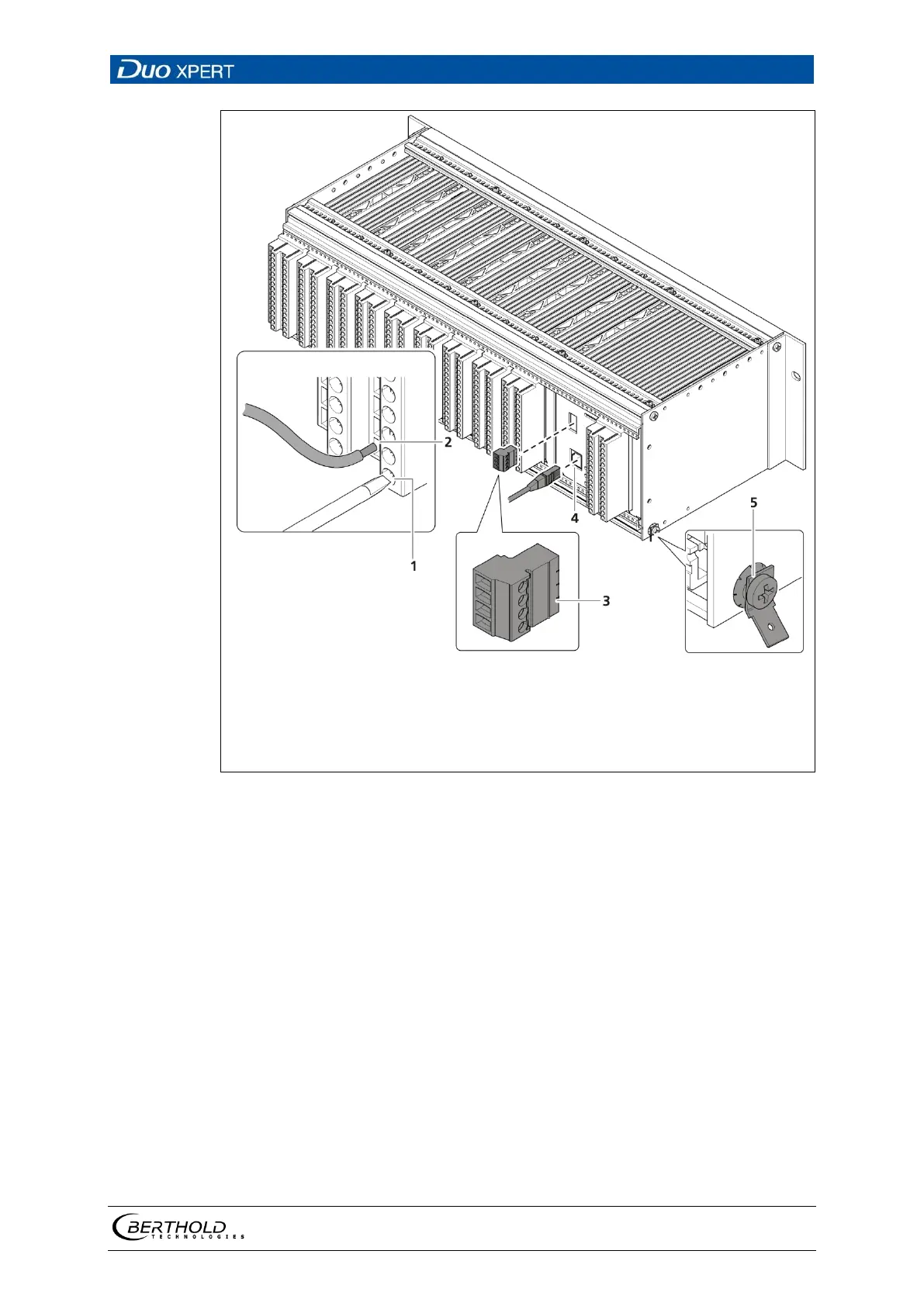
Clamping screw (M2.5)
Opening terminal connection
4-pin master/slave plug (only master EVU)
terminals 41-44
RJ45 connector (network)
PE connection
24 Electrical connection in the 19″ component rack (Ex.: 1xMaster,
9xSlave)
1. Connect the lines to the clamp blocks according to assignment (chap. 5.6.2 or
5.6.3).
2. Open the clamping screw (Fig. 24, item 1) and insert the stripped wire (min. 8
mm).
The terminal connections are designed for wires with a conductor cross-sec-
tion from 0.2 mm² to 2.5 mm².
3. Screw the clamping screws with a tightening torque of 0.4 - 0.5 Nm.
4. Plug in the master/slave plug and reconnect the lines in accordance with as-
signment (chap. 5.6.1 and chap. 5.6.2 or chap. 5.6.3).
5. Plug the network plug into the RJ45 socket (Fig. 24, item 4) (optional).
6. Check the correct connection of the PE conductor (Fig. 24, item 5).