3
60
5
6
6
7
5
8
ENGINE CHECKS AND ASSEMBLY
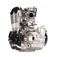
Application of forks to gearwheels.
Introduce the forks together with the guide bush-
es on the gear tracks. Namely: the smaller fork 5
drives the sliding gear on the primary unit, while
the other two (6) drive the sliding gears on the
secondary unit.
Note: the two forks 6 are interchangeable and
their positioning is univocal, since the drive pin
must face the desmodromic device. Place the
forks in their original positions if none of the
components are replaced.
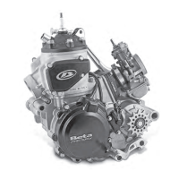
Insert the desmodromic device in the specific
bearing. In order to do this, the cam stop lever
7 must be rotated towards the top part of the
engine.
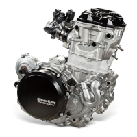
Position the fork 5 of the primary unit in the cen-
tral guide of the desmodromic device 8, insert the
fork pin inside the fork and insert the pin in its
specific seat in the crankcase half.
Insertion of desmodromic device in the specific bearing.
Note the rotation of the gear stop lever.
Place fork 5 of the primary unit in the central guide
of desmodromic device 8.