35 support@solowavedesign.com
2 x #8 x 1-3/4” Wood Screw
2 x #12 x 2” Pan Screw
(with 3/16” at washer)
2 x #8 x 3” Wood Screw
HardwareWood Parts
4 x 1/4 x 2” Hex Bolt
(1/4” lock washer, 1/4” at washer, 1/4” t-nut)
1 x 1/4 x 4” Hex Bolt
(1/4” lock washer, 1/4” at washer, 1/4” t-nut)
1 x 1/4 x 4-1/2” Hex Bolt
(1/4” lock washer, 1/4” at washer, 1/4” t-nut)
H2
1 x Middle Front 1 x 5 x 65-5/8”
1 x SL Post 2 x 4 x 32-1/2”
2125
2112
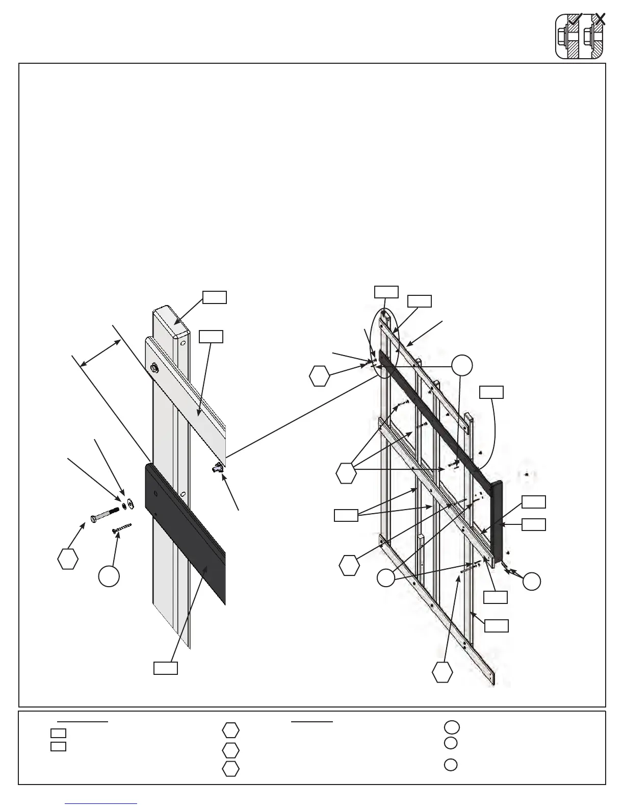
Step 9: Front Wall Assembly
Part 4
F:Looselyattach(2125)MiddleFrontontheoutsideoftheassemblytoboth(2153)Postsandboth(2154)Front
Postswith4(H2)1/4x2”HexBolts(withlockwasher,atwasherandt-nut).(g.9.4)
G: Makesurethedistancebetween(2114)TopFrontand(2125)MiddleFrontis9-1/2”thenattach(2125)
MiddleFronttoeach(2153)Postwith2(S15)#8x1-3/4”WoodScrews.TightentheboltsfromStepF.(g.9.4
and9.5)
H:Attheendsof(2125)MiddleFrontand(2120)FloorFrontBackplace(2112)SLPostasshowning.9.4.
Attach(2112)SLPostto(2124)FrontFloorwith1(H5)1/4x4-1/2”HexBolt(withlockwasher,atwasherand
t-nut)inthebottomholeand1(S7)#12x2”PanScrew(withatwasher)inthetopholeandto(2125)Middle
Frontwith1(H4)1/4x4”HexBolt(withlockwasher,atwasherandt-nut)inthetopholeand1(S7)#12x2”
PanScrew(withatwasher)inthebottomhole.(g.9.4)
I:Attach(2112)SLPostto(2120)FloorFrontBackwith2(S4)#8x3”WoodScrews.(g.9.4)
Outside View
1/4”lock
washer
1/4”at
washer
1/4”t-nut
S15
Fig. 9.4
2125
H2
H4
H5
S15
S7
2153
S4
2112
2124
2154
2153
with3/16”
atwasher
H4
S7
H5
S4
2120
Fig. 9.5
H2
S15
H2
2153
2125
2114
2114
1/4”t-nut
1/4”at
washer
1/4”lock
washer
9-1/2”