KB / KB-UL (E4 + E6) 10/2021 page 113/147
19. Options
19.1 APT-COM™ 4 Multi Management Software (option)
The chamber is regularly equipped with an Ethernet interface (7) that can connect the BINDER APT-COM™
4 Multi Management Software. The MAC Address is indicated under Menu > Settings > Network settings >
Show network settings (chap. 12.9). The actual temperature, and fan speed values are given in adjustable
intervals. Programming can be performed graphically via PC. Up to 100 chambers can be cross linked. For
further information, refer to the APT-COM™ 4 operating manual.
19.2 Data logger kit (option)
The BINDER Data Logger Kit offers an independent long-term measuring system for temperature, available
for different temperature ranges.
The BINDER Data Logger is equipped with a keyboard and a large LCD display, alarm functions and a
real-time function. Measurement data are recorded in the Data Logger and can be read out after the meas-
urement via the RS232 interface of the Data Logger. It offers a programmable measuring interval and
permits storing up to 64000 measuring values. Reading out is done with the Data Logger evaluation soft-
ware. You can give out a combined alarm and status protocol directly to a serial printer.
Data Logger Kit T 220: Measuring sensor for the temperature values of the chamber: Temperature range
-90 °C / 194 °F up to +220 °C / 428 °F.
For detailed information on installation and operation of the BINDER Data Logger, please
refer to the mounting instructions Art. No. 7001-0204 and to the original user manual of the
manufacturer, supplied with the data logger.
19.3 Interior lighting
Opening the door activates the interior lighting. When closing the door, the interior lighting goes off again.
19.4 Zero-voltage relay alarm output (option)
With this option the chamber is equipped with a zero-voltage relay alarm contact which serves to transmit
alarms to a central monitoring facility.
The connection is realized as a DIN socket. A suitable DIN plug is enclosed.
With KB / KB-UL (E4) 53, 115 the DIN (6) socket is located on the chamber rear.
With KB / KB-UL (E6) 240, 400, 720, the DIN socket (6) is located in the right lateral control panel.
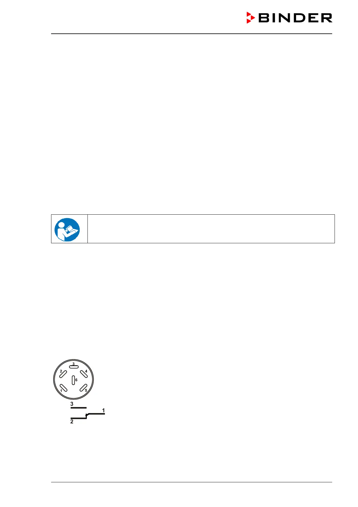
Figure 13: Pin configuration of the DIN socket (6)
ALARM
Pin 1: Pole, Pin 2: Break relay, Pin 3: Make contact
In case there is no alarm, contact 1 closes with contact 3.
Closing contact 1 with contact 2 switches the zero-voltage relay alarm output.