KB / KB-UL (E4 + E6) 10/2021 page 127/147
23. Technical description
23.1 Factory calibration and adjustment
This chamber was calibrated and adjusted in the factory. Calibration and adjustment were performed using
standardized test instructions, according to the QM DIN EN ISO 9001 system applied by BINDER (certified
since December 1996 by TÜV CERT). All test equipment used is subject to the administration of measure-
ment and test equipment that is also constituent part of the BINDER QM DIN EN ISO 9001 systems. They
are controlled and calibrated to a DKD-Standard at regular intervals.
Repeated calibrations are recommended in periods of 12 months.
23.2 Over current protection
The chambers are equipped with an internal fuse (over-current release) not accessible from outside. If this
fuse is blown, please contact an electronic engineer or BINDER Service.
In addition, the chambers KB 53-UL / 115-UL are protected by a chamber-protection against over current,
accessible from the outside. It is located at the rear of the chamber below the strain relief of the power cord.
The fuse holder is equipped with a fuse clip 6.3 x32 mm. Replace this fuse only with a substitute of the
same ratings. Refer to the technical data of the respective device type. If this fuse is blown, please inform
an electronic engineer or BINDER service.
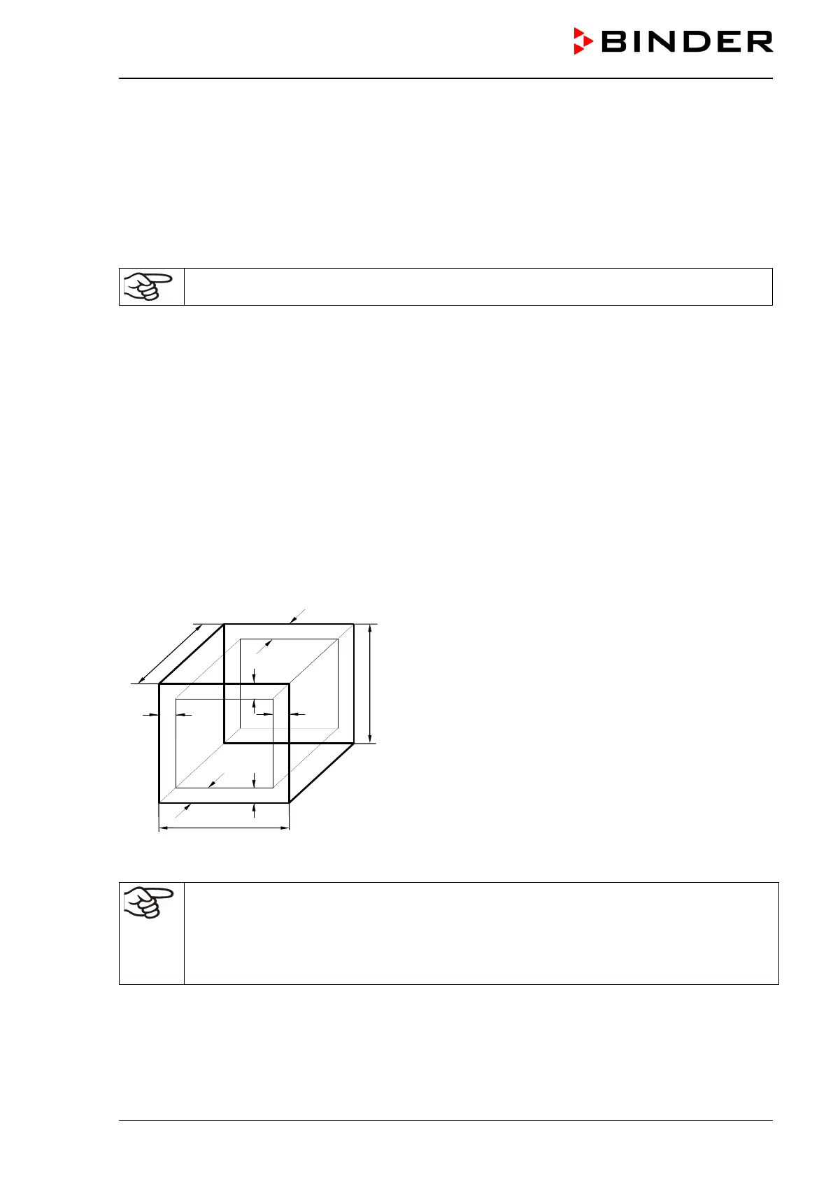
23.3 Definition of usable volume
The usable volume illustrated below is calculated as follows:
A, B, C = internal dimensions (W, H, D)
a, b, c = wall separation
a = 0.1*A
b = 0.1*B
c = 0.1*C
V
USE
= (A - 2 * a) * (B - 2 * b) * (C - 2 * c)
Figure 15: Determination of the usable volume
The technical data refers to the defined usable volume.
Do NOT place samples outside this usable volume.
Do NOT load this volume by more than half to enable sufficient airflow inside the chamber.
Do NOT divide the usable volume into separate parts with large area samples.
Do NOT place samples too close to each other in order to permit circulation between them
and thus obtain a homogenous temperature distribution.