KB / KB-UL (E4 + E6) 10/2021 page 114/147
Maximum loading capacity of the switching contacts: 24V AC/DC – 2.5A
DANGER
Electrical hazard through overload of contacts.
Deadly electric shock. Damage to the switching contacts and connection socket.
∅ Do NOT exceed the maximum switching load of 24V AC/DC – 2.5A.
∅ Do NOT connect any devices with a higher loading capacity.
The zero-voltage relay alarm contact is activated in case of temperature tolerance range alarm and in case
of a power failure.
Error when icon is displayed
Switching the alarm contact
Power failure immediately
Temperature tolerance range alarm 10 minutes after the error occurred
A temperature alarm message will remain visible on the controller display during the whole time of the alarm
transmission via the zero-voltage relay contact.
As soon as the cause of the alarm is rectified, you can reset the alarm transmission via the zero-voltage
relay outputs together with the alarm message at the controller display by pressing the “RESET” key.
In case of a power failure, transmission of the alarm via zero-voltage relay outputs remains active for the
duration of the power failure. Afterwards, both contacts will close automatically.
When using the APT-COM™ 4 Multi Management Software (option, chap. 19.1) via the Ether-
net interface of the chamber for data acquisition, the alarm message is not recorded in the
APT-COM™ protocol.
Set the tolerance limits for limit alarms by APT-COM™ 4 separately in the AlarmCenter.
You can switch on and off the alarm output for test purpose. To access this function, select
Menu > Optional equipment > Alarm output temperature (chap. 7.3).
19.5 Zero-voltage relay control outputs (may be available via BINDER INDIVIDUAL
Customized Solution)
The zero-voltage relay control outputs 1, 2 und 3 are used to switch any device connected via a DIN socket
on the chamber rear. They permit turning on and off individually the connected devices by the controller.
They can be programmed in fixed value entry mode (chap. 7.2) as well as in the time program editor (chap.
9.3.7) or the week program editor (chap. 10.3.6) via the operation lines.
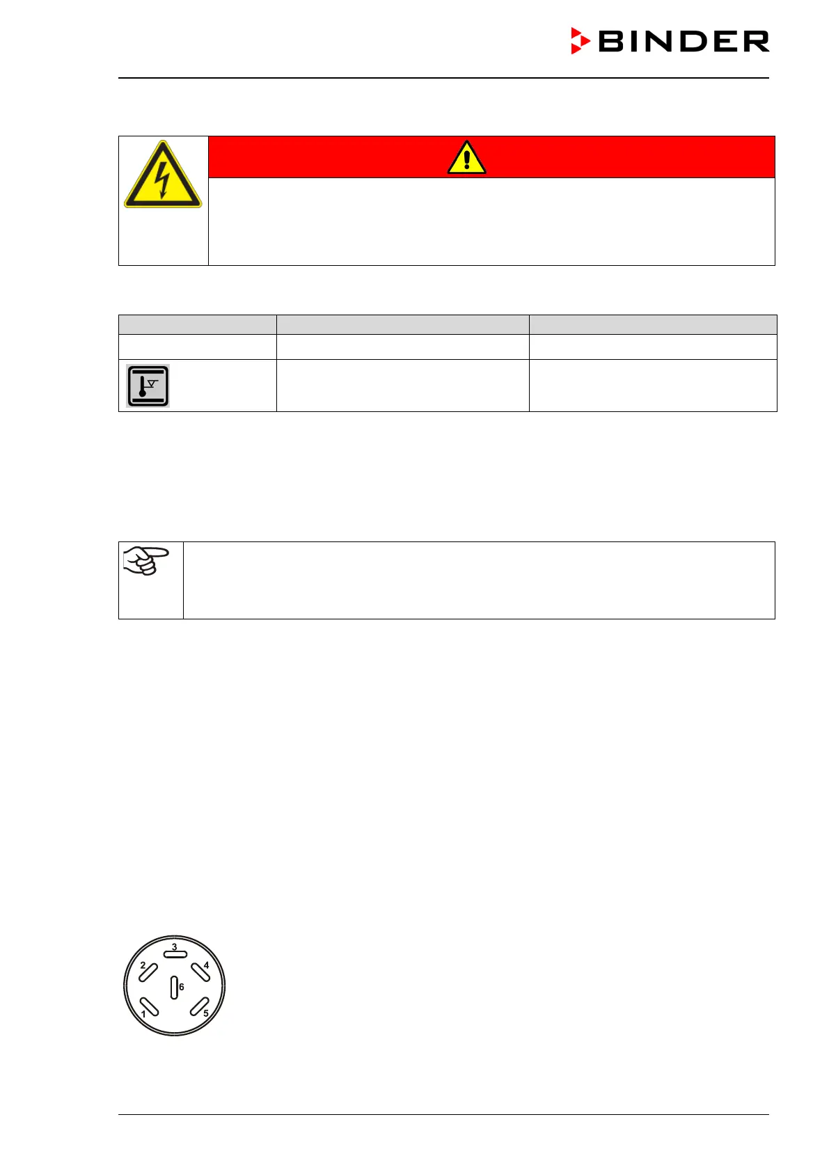
The connection is realized as a DIN socket. A suitable DIN plug is enclosed.
With KB / KB-UL 53 / 115 (E4) the DIN (5) socket is located on the chamber rear.
With KB / KB-UL 240 / 400 / 720 (E6) the DIN socket (5) is located in the right lateral control panel.
Figure 14: Pin configuration of the DIN socket (5)