34 CT-600-2
Use table in section 13.5 for reference. Actual scaling may differ and must be configured according to
sensor types used.
5. Configure analog outputs: Config.Type AO
Use table in section 13.5 for reference. Actual output types may differ and must be configured
accordingly. Take in mind that not all analog outputs are configurable.
6. Configure Ethernet (remote access and Modbus-TCP): Network Config.
Set IP-Address, Subnet mask and Gateway Address.
7. Configure RS485-1 and 2 (Modbus-RTU)
Set Modbus address for M172 to 10 for communication with PLC in ACP LINK panel.
Leave other settings to default.
8. Log out of Settings by pressing back key until Main Screen is shown.
9.7 Configuration, variable speed drives (VSD)
This section describes the configuration of the variable speed drive that can be delivered as optional
equipment by BITZER (WEG Variable Speed Drive CFW11). If the customer uses a different brand or type,
not delivered by BITZER, then below section can be used as guideline.
Check of direction of rotation with VSD
Direction of rotation is imperative to check as the first thing, before operating the compressor. This can be
done with a VSD set to operate at extremely low speed.
Configure the VSD to run very low speed (2 - 3 Hz). Have an assistant observe the coupling of the motor,
then set the VSD to run very briefly (max 5 sec.). If the compressor is running in the same direction as the
arrow cast on the housing near the coupling is pointing, the direction of rotation is confirmed correct. If the
direction of rotation is incorrect, this must be corrected by changing motor cable connections.
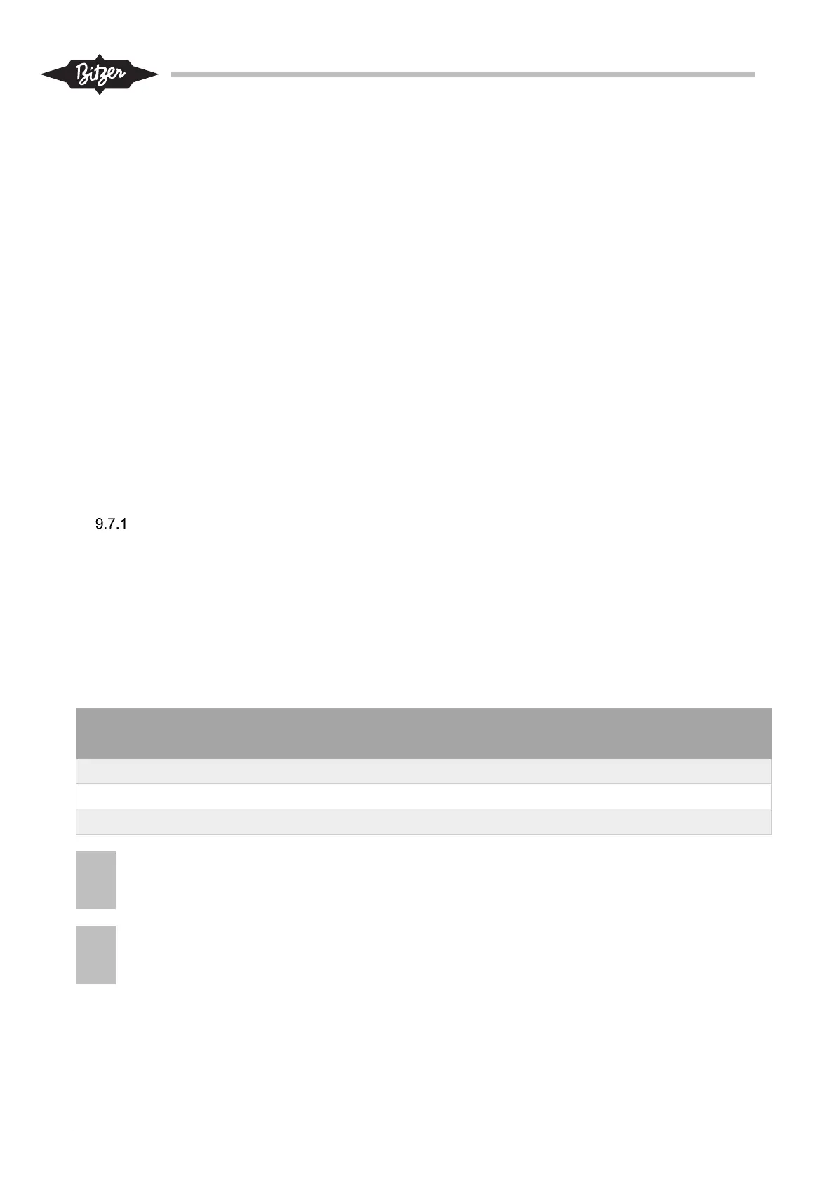
On WEG VSD type CFW11, this test can be done by setting below parameters:
Parameter WEG Par.
No.
Value Note
JOG-Reference 123 150 150rpm corresponds to 2.5Hz
LOC/REM Selection Src 220 0: Always LOC Set back to “1: Always REM”, after test!
LOC JOG Selection 225 1: JOG Key Set back to “0: Disable”, after test!
NOTICE
Do not change the direction of rotation with configuration of the parameters of the VSD, but only
change motor cable connections to correct, if necessary.
NOTICE
After check of rotation direction, assure that the VSD is again configured according to the instructions and
settings mentioned in section 9.7.2.
!
!
!
!