CT-600-2 51
Compressor modules (C1, C2, C3)
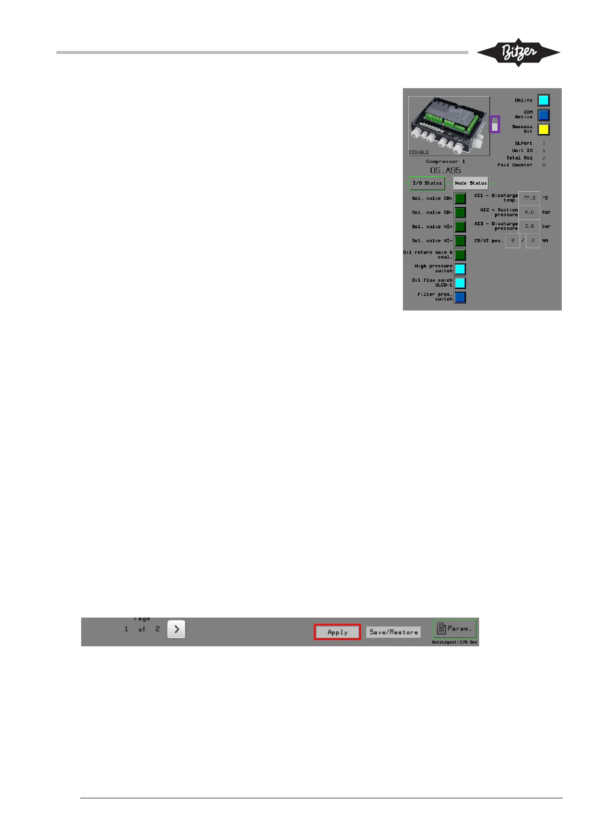
The compressor modules (CM-SW-01) communicate with the ACP
LINK PLC over Modbus RTU. The node addresses are configured
with BEST software on the module (see 9.4). The network
communication between the PLC and the compressor module
must be enabled by pressing on the button with picture of the
module in the right side of the screen [1]. The lamps and
information next to the button show the communication status. The
lamp “online” must light continuously to indicate proper
communication. For the communication to be successful, it is
necessary to have the configuration and parameters for PLC and
modules set up correctly. See sections 9.2 and 9.4 on how to
configure.
The right side of the page also shows two tabs with values of the
inputs and outputs and status for relevant parameters on the
compressor.
Electrical panel IO-module (IOSP)
The electrical panel IO-module also communicates with the ACP LINK PLC over Modbus RTU and connects
the digital and analog input and output signals from the plant to the ACP. The node address must be set
correctly on the M172 module, see section 9.6. The communication to the module must be enabled by
pressing the button with picture of the module in the right side of the screen, similarly as for the compressor
modules.
The user can monitor the status of the different inputs and outputs to/from the module with the three tabs on
the right side of the page.
Oil and economizer system modules (OAHC & ECOSYS)
The CM-IO module on the oil separator and the optional economizer function as a remote IO modules and
communicate to the ACP LINK PLC over Modbus RTU. Setup and connection is similar as described above
for the compressor modules.
10.11 Parameters and timers screen (Param.)
The screen to view and change parameter and timer settings is accessed at the right-hand bottom corner of
the HMI. The top of the Parameter screen shows buttons that link to different sub sections. Each sub section
can consist of multiple pages that can be access using the arrow buttons in the bottom of the page.
See section 9.2, 9.3 and 0 for further information on the different parameters. Section 11 describes the
different functions in the ACP LINK PLC including the parameters and timers used for each function.
When logged in as “Service” it is important to note, that after any change has been made to a parameter or a
timer, the “Apply” button at the bottom of the screen must be pressed for the change to take effect. If the user
switches to a different screen without pressing “Apply”, the settings are discarded.
1